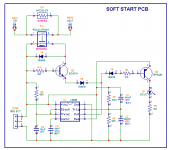
This circuit is autonomous and does not need any external support to work. It is based on the well-known timer NE555 and an NTC which could be changed according to the size of the transformer. When the power switch is turned on, the mains voltage passes through the NTC while at the same time the NE555 is triggered and the blue LED is blinking for 1.5 second. After that, the output of 555 is turned steady ON, it activates the power relay which in sequence shorts the NTC and so the mains voltage passes through its contacts. The blue LED now is turned ON. This circuit is very rugged and tested for 12 years of problem-free operation in any condition.
Attachments
Last edited:
[special=The relay should be a double pole relay as a break in the speaker ouput as well is desirable.]%[/special]
Thanks a lot for the reply.
Why this?
I know that a separate DC protect etc circuit is used for speaker protection. It is triggered when the 555 of trafo is turned steady ON. If you want the related circuit let me know.
Thanks a lot for the reply.
Why this?
I know that a separate DC protect etc circuit is used for speaker protection. It is triggered when the 555 of trafo is turned steady ON. If you want the related circuit let me know.
Well I did read the post incorrect... Jon Snell is suggesting to open the speaker connection during the soft start period. That is good as no power on phenomenon (possibly a loud plop) will be heard. The question is if the timing will be OK.
Last edited:
Even if it should be desirable, is the insulation between the poles of a double-pole relay sufficient to also break the speaker output and do you want to have the speaker wiring run right next to mains wiring?
Good one!
Despite being often omitted in modern designs disabling power on/off phenomenons is quite user friendly.
Despite being often omitted in modern designs disabling power on/off phenomenons is quite user friendly.
Last edited:
From my experience, within 3sec the inrush current is zeroed and the reservoir capacitors are fully charged yet for a 1KW trafo. Your spot is good, but (I checked it just now) I have configured the speaker protect to close the relays after 5 sec! I've built these projects 12 years ago, but I could confirm that is very trustable.
OK, you could bring your idea with a schematic, please.
OK, you could bring your idea with a schematic, please.
Last edited:
For even more simplicity Apart from purchasing and fitting), but with perhaps an aesthetic disadvantage, you could use an industrial 3 position mains switch with make-before-break contacts, and positions for off, pre-charge, on. Use an NTC that can manage continuous operation.
Last edited:
It is wise the use of a separate relay for speaker protection. It is also common practice the use of a relay to short the NTC because it will run very hot.
I have used a 10ohm resistor as pre-charge resistor on the primary. This is then bypassed with a relay that has it's coil connected to the rectifier caps. I used zeners in series with the relay coil to tune the on-voltage. Very simple, and worked well.
I have used a 10ohm resistor as pre-charge resistor on the primary. This is then bypassed with a relay that has it's coil connected to the rectifier caps. I used zeners in series with the relay coil to tune the on-voltage. Very simple, and worked well.
That brilliant and super simple, I was just trying to find a solution with as few parts and little space as possible. Will probably change your 10 ohm resistor for a 10 ohm NTC mostly because it takes less space.
What values (rail voltage, zener voltage and relay volt) are you working with and what delay do you get?
Just to get an idea before ordering the parts, I understand I will need to test/tweak based on my setup.
Sure, NTC should be even better, especially if it's a class A amp as load.
One side of the coil via zener to one rail, and same on the other side of the coil to the other rail.
I think I used a 24V relay and 35V zeners, maybe a small current limiting resistor in series could be used too, but relays normally engage at a much lower voltage than the marked coil voltage.
Delay was short, but that depends on the series resistor and the capacity on the cap bank. I think I 'tuned it' for the relay to engage when rail to rail voltage was abt 10V under nominal.
- Home
- Amplifiers
- Power Supplies
- Very simple soft start for high power trafos