Hello,
I would like to share a few amplifier schematics that I have designed. I have been involved in the construction of radio equipment for some time, mainly receivers, transceivers, and measurement instruments. The schematics I am sharing below mark my debut in audio electronics.
It all started with my experiments with a simple Class A amplifier. Due to the current war in my country conditions limiting component availability, I had to use inexpensive n-channel MOSFETs and general-purpose BJT transistors. The circuit was simplified to use the minimum number of components.

This is a Shiklai pair Q1U2 loaded with a current source at Q2U1. The IRF4905 with a 75A current source is somewhat excessive, but I didn't have any other p-channel transistors on hand. You can use almost any MOSFET for U2. I used counterfeit ones I received from AliExpress (instead of IRFZ24).
The gain is set by the ratio of resistors R6R4 and is 4. It's not advisable to increase it further as it increases distortion.
U1U2 requires a heat sink with an area of 800-1000 square cm as they heat up significantly.
Resistor R1 should be set to half of the supply voltage at the amplifier's output.
The maximum power output is 2.7 watts, and the current consumption is 1A. The transistors are installed on the same heat sink without insulating pads.
The output signal is almost distortion-free up to 80-100kHz. The -3dB bandwidth is 300kHz.
The amplifier has fairly low distortion levels, with the second harmonic predominating in the spectrum.

The amplifier sounds decent, but I was not satisfied with its low efficiency of 10% and its low output power. Therefore, I introduced additional feedback, resulting in the following schematic.

The maximum power output increased to 5.6 watts, and the efficiency increased to 23%. Distortion remained nearly unchanged. The spectrum, as in the previous circuit, shows a decreasing trend, with the second harmonic being more prominent than the third.

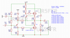
Based on this amplifier, I decided to make a amplifier working in Class B. The resulting schematic is as follows:

Resistor R10 sets the idle current at 200mA. Using the C4R8R9 allows the output power to be raised to 10 watts.
Distortion does not exceed 0.1% at various volume levels. The distortion spectrum is typical for a push-pull amplifier, with the level of the third harmonic higher than the second. A square wave signal with a frequency of 20kHz amplifies without visible distortion. No distortion typical of Class B amplifiers is observed when the signal crosses zero. The -3dB bandwidth is 200kHz, but starting at around 50kHz, the shape of the sinusoidal signal distorts - asymmetry becomes noticeable. It's possible that using transistors with lower gate capacitance will improve this situation.

Resistor R12 can have a resistance other than zero. I experimented with a value of 0.5 ohms, which has an interesting effect: distortion levels increase slightly, but the level of the second harmonic increases by approximately 6-10dB more than the third. At the same time, the level of the third and higher harmonics remains unchanged. Presumably, the higher level of the second harmonic will mask the third harmonic. It should also be noted that this slightly reduces the maximum output power (by approximately 8-10%).
It's quite possible that these schematics could be of interest and benefit to others.
73! de UR5FFR
I would like to share a few amplifier schematics that I have designed. I have been involved in the construction of radio equipment for some time, mainly receivers, transceivers, and measurement instruments. The schematics I am sharing below mark my debut in audio electronics.
It all started with my experiments with a simple Class A amplifier. Due to the current war in my country conditions limiting component availability, I had to use inexpensive n-channel MOSFETs and general-purpose BJT transistors. The circuit was simplified to use the minimum number of components.
This is a Shiklai pair Q1U2 loaded with a current source at Q2U1. The IRF4905 with a 75A current source is somewhat excessive, but I didn't have any other p-channel transistors on hand. You can use almost any MOSFET for U2. I used counterfeit ones I received from AliExpress (instead of IRFZ24).
The gain is set by the ratio of resistors R6R4 and is 4. It's not advisable to increase it further as it increases distortion.
U1U2 requires a heat sink with an area of 800-1000 square cm as they heat up significantly.
Resistor R1 should be set to half of the supply voltage at the amplifier's output.
The maximum power output is 2.7 watts, and the current consumption is 1A. The transistors are installed on the same heat sink without insulating pads.
The output signal is almost distortion-free up to 80-100kHz. The -3dB bandwidth is 300kHz.
The amplifier has fairly low distortion levels, with the second harmonic predominating in the spectrum.
The amplifier sounds decent, but I was not satisfied with its low efficiency of 10% and its low output power. Therefore, I introduced additional feedback, resulting in the following schematic.
The maximum power output increased to 5.6 watts, and the efficiency increased to 23%. Distortion remained nearly unchanged. The spectrum, as in the previous circuit, shows a decreasing trend, with the second harmonic being more prominent than the third.
Based on this amplifier, I decided to make a amplifier working in Class B. The resulting schematic is as follows:
Resistor R10 sets the idle current at 200mA. Using the C4R8R9 allows the output power to be raised to 10 watts.
Distortion does not exceed 0.1% at various volume levels. The distortion spectrum is typical for a push-pull amplifier, with the level of the third harmonic higher than the second. A square wave signal with a frequency of 20kHz amplifies without visible distortion. No distortion typical of Class B amplifiers is observed when the signal crosses zero. The -3dB bandwidth is 200kHz, but starting at around 50kHz, the shape of the sinusoidal signal distorts - asymmetry becomes noticeable. It's possible that using transistors with lower gate capacitance will improve this situation.
Resistor R12 can have a resistance other than zero. I experimented with a value of 0.5 ohms, which has an interesting effect: distortion levels increase slightly, but the level of the second harmonic increases by approximately 6-10dB more than the third. At the same time, the level of the third and higher harmonics remains unchanged. Presumably, the higher level of the second harmonic will mask the third harmonic. It should also be noted that this slightly reduces the maximum output power (by approximately 8-10%).
It's quite possible that these schematics could be of interest and benefit to others.
73! de UR5FFR
In the last amplifier with two diodes in class B, it is possible to adjust the idle current by changing the resistor R10. If you increase it from 4.7 ohms to 10 ohms, the current will increase from 220mA to 430mA.

Distortions have slightly decreased at low volume levels of 2-2.8Vrms (1-1.5W) because the amplifier operates almost in pure class A, where harmonic distortion is either absent or its level is 15-20dB lower than the second.
0.7W 2Vrms @6R
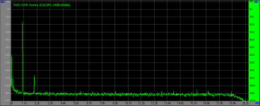
However, at higher volume levels, the distortion spectrum has changed significantly. Now, the second harmonic dominates, and the third one has a level 10dB lower. For example, here is the spectrum before and after increasing the idle current at different output power levels and different idle currents.
4.2W 5Vrms @6R I0=220mA
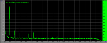
4.2W 5Vrms @6R I0=430mA
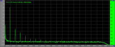
6W 6Vrms @6R I0=220mA
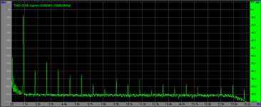
6W 6Vrms @6R I0=430mA
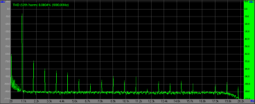
This trend persists at all output levels, even up to the maximum before the onset of limiting.
8.2W 7v @6R I0=220mA
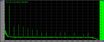
8.2W 7v @6R I0=430mA
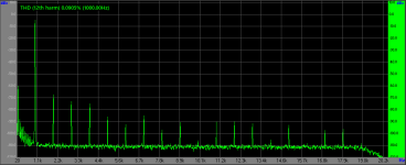
Another positive aspect is the reduction of sine wave distortions. With an idle current of 220mA, distortion of the sine wave shape was observed after 50kHz. With an increase in idle current to 430mA, such distortions are observed after 100kHz.

Distortions have slightly decreased at low volume levels of 2-2.8Vrms (1-1.5W) because the amplifier operates almost in pure class A, where harmonic distortion is either absent or its level is 15-20dB lower than the second.
0.7W 2Vrms @6R

However, at higher volume levels, the distortion spectrum has changed significantly. Now, the second harmonic dominates, and the third one has a level 10dB lower. For example, here is the spectrum before and after increasing the idle current at different output power levels and different idle currents.
4.2W 5Vrms @6R I0=220mA

4.2W 5Vrms @6R I0=430mA

6W 6Vrms @6R I0=220mA

6W 6Vrms @6R I0=430mA

This trend persists at all output levels, even up to the maximum before the onset of limiting.
8.2W 7v @6R I0=220mA

8.2W 7v @6R I0=430mA

Another positive aspect is the reduction of sine wave distortions. With an idle current of 220mA, distortion of the sine wave shape was observed after 50kHz. With an increase in idle current to 430mA, such distortions are observed after 100kHz.
Hi,
Your design makes me think of the zen amplifiers by Nelson Pass. Here is a link to a variation with a controlled current source, wich makes the amplifier work more like a push-pull, might be of interest to you: https://www.passdiy.com/project/amplifiers/zen-variations-2
Your design makes me think of the zen amplifiers by Nelson Pass. Here is a link to a variation with a controlled current source, wich makes the amplifier work more like a push-pull, might be of interest to you: https://www.passdiy.com/project/amplifiers/zen-variations-2
Hi,
Yes, you right, there are some similarities, but my implementation is somewhat different. I looked at the patent for Nelson's circuit, but did not find any variants of the circuit that were similar to mine. I'll try to assemble this version of the circuit to make comparative measurements.
By the way, while reading similar patents to improve the performance of amplifiers operating in class A, I found patent US6434243. Here is a diagram from it
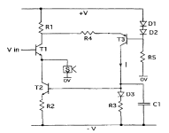
D1D2T3 form a current source controlled by voltage, which depends on the current of transistor T1 - when T1 opens, the current through T3 decreases and vice versa. D3T2 form a current mirror. The circuit is quite simple and can be implemented on both BJT and MOSFET.
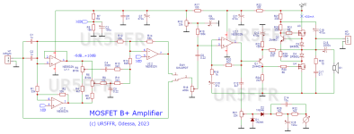
Right now I'm working on an amplifier with two diodes. Its interesting feature is that the output stage transistors are never completely closed. This definitely reduces distortion. In addition, it has strict stabilization of the quiescent current, which does not depend on the temperature and type of output transistors used.
I supplemented this amplifier with a switchable tone block using a non-standard scheme
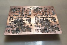
I assembled this circuit on a printed circuit board. Not very nice like the green factory PCBs but done quickly 🙂
I am very pleased with the result of such a simple circuit that requires no adjustment and produces excellent sound.

Yes, you right, there are some similarities, but my implementation is somewhat different. I looked at the patent for Nelson's circuit, but did not find any variants of the circuit that were similar to mine. I'll try to assemble this version of the circuit to make comparative measurements.
By the way, while reading similar patents to improve the performance of amplifiers operating in class A, I found patent US6434243. Here is a diagram from it

D1D2T3 form a current source controlled by voltage, which depends on the current of transistor T1 - when T1 opens, the current through T3 decreases and vice versa. D3T2 form a current mirror. The circuit is quite simple and can be implemented on both BJT and MOSFET.
Right now I'm working on an amplifier with two diodes. Its interesting feature is that the output stage transistors are never completely closed. This definitely reduces distortion. In addition, it has strict stabilization of the quiescent current, which does not depend on the temperature and type of output transistors used.
I supplemented this amplifier with a switchable tone block using a non-standard scheme

I assembled this circuit on a printed circuit board. Not very nice like the green factory PCBs but done quickly 🙂
I am very pleased with the result of such a simple circuit that requires no adjustment and produces excellent sound.


H
HAYK
https://www.diyaudio.com/community/...317-efficient-and-simple.402477/#post-7432268
Post in thread 'Single supply Low Power MOSFET Class A/AB amp' https://www.diyaudio.com/community/...wer-mosfet-class-a-ab-amp.403993/post-7475897
Post in thread 'Single supply Low Power MOSFET Class A/AB amp' https://www.diyaudio.com/community/...wer-mosfet-class-a-ab-amp.403993/post-7475897
HAYK, judging by what I looked at, your circuit with LM317 has a higher level of distortion than the one I proposed. In addition, it has a lower maximum output power at the same supply voltage. Perhaps you should try adding a BJT transistor stage like mine and negative feedback - this should reduce distortion without significantly degrading the dynamic and spectral characteristics of the amplifier.
H
HAYK
Oops, sorry for my carelessness 🙂 Did you assemble this circuit with a current source on a MOSFET and were there any measurements of it?
H
HAYK
The output stage was before a SRPP source follower with a 600/10k input transformer. I used it about a month, very pleasant. The input and the VAS is from JLH1969.
From experiments with quiescent current it follows that as it increases, distortion decreases. Why not increase it to such a value that the amplifier will operate completely in Class A?
With a value of R61 of 18 ohms, the quiescent current will increase to 900 mA.
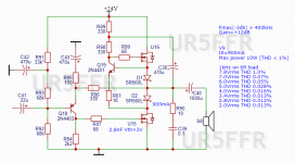
This reduces distortion. The maximum power remains unchanged. Here is a comparison of the operation of this circuit at various quiescent currents.

It is interesting to compare the characteristics of this circuit with the Class A amplifier with a controlled current source, which I presented at the very beginning of this topic - here is its circuit.
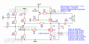
It can be seen that the circuit with diodes has a much higher maximum power - 10W versus 6W, and less distortion.
It may seem that diodes can be replaced with small value resistors. But this worsens the parameters of the amplifier - the maximum output power drops and distortion increases. For example, at 7 volts at the output, a circuit with resistors already has 1% THD, while an amplifier with diodes has 0.07% THD.
All distortion values are derived from measurements, not simulations. Unfortunately, my test bench limits me to about 0.005%-0.01% THD, so actual distortion values at levels less than 0.02% THD may actually be lower.
With a value of R61 of 18 ohms, the quiescent current will increase to 900 mA.

This reduces distortion. The maximum power remains unchanged. Here is a comparison of the operation of this circuit at various quiescent currents.

It is interesting to compare the characteristics of this circuit with the Class A amplifier with a controlled current source, which I presented at the very beginning of this topic - here is its circuit.

It can be seen that the circuit with diodes has a much higher maximum power - 10W versus 6W, and less distortion.
It may seem that diodes can be replaced with small value resistors. But this worsens the parameters of the amplifier - the maximum output power drops and distortion increases. For example, at 7 volts at the output, a circuit with resistors already has 1% THD, while an amplifier with diodes has 0.07% THD.

All distortion values are derived from measurements, not simulations. Unfortunately, my test bench limits me to about 0.005%-0.01% THD, so actual distortion values at levels less than 0.02% THD may actually be lower.
Last edited:
Congratulations UR5FFR on a nice little amp! I love the simplicity and the diode arrangement is very clever. I'v been working on similar mosfet output stages myself and have ordered a bunch of schottky diodes to experiment with your configuration 🙂
I was wondering what mosfets you used as it strikes me as input gate capacitance is an important factor and would result in much higher distortion at higher frequency's. have you tried an emitter follower to drive the gate of the lower mosfet? this drops overall distortion considerably in LTSpice.
I was wondering what mosfets you used as it strikes me as input gate capacitance is an important factor and would result in much higher distortion at higher frequency's. have you tried an emitter follower to drive the gate of the lower mosfet? this drops overall distortion considerably in LTSpice.
Last edited:
I have always liked BJT/MOSFET Sziklai pair amps. The specs lend themselves to a very powerful Class A headphone amp.
Nice work and great explanation of the progression and super measurements. All done with a war raging on outside your doorsteps. It is very inspiring.
Your countrymen also managed to be one of ten Global Winners of the 2023 NASA SpaceApps Challenge.
https://www.spaceappschallenge.org/2023/find-a-team/storm-prophet/
They developed a machine learning neural net algorithm to predict solar storms from data from the DSCOVR spacecraft.
There were 58,000 participants from 152 countries who participated in a 2 day hackathon with over 5500 team submissions. It was truly competitive and I was amazed to see a team of young students from Kiev win.
Last edited:
I tried using an emitter follower, but it didn't make much difference, so I abandoned it in favor of a simpler circuit. The gate capacitance certainly affects the parameters of the amplifier. In the final version I used 1.4 nf transistors and got very good results. I would recommend using field effect transistors with a gate capacitance of no more than 1.5 nf.Congratulations UR5FFR on a nice little amp! I love the simplicity and the diode arrangement is very clever. I'v been working on similar mosfet output stages myself and have ordered a bunch of schottky diodes to experiment with your configuration 🙂
I was wondering what mosfets you used as it strikes me as input gate capacitance is an important factor and would result in much higher distortion at higher frequency's. have you tried an emitter follower to drive the gate of the lower mosfet? this drops overall distortion considerably in LTSpice.
Unfortunately, I cannot tell you the type of transistors used - this is a fake that was sent to me from aliexpress. I think these are some fairly cheap power field-effect transistors. You can take suitable ones from the IRF series. In general, the circuit is not critical to the type of transistors used.I have always liked BJT/MOSFET Sziklai pair amps. The specs lend themselves to a very powerful Class A headphone amp.Nice work and great explanation of the progression and super measurements.
I have always liked BJT/MOSFET Sziklai pair amps. The specs lend themselves to a very powerful Class A headphone amp.
Nice work and great explanation of the progression and super measurements.
It is possible that using Sziklai pairs at the output of the amplifier will improve its performance, but I have not tested this and am unlikely to be able to do so in the near future.
All done with a war raging on outside your doorsteps.
Unfortunately, war is not only on the doorstep, but literally over my head. Despite the fact that I am several hundred kilometers from the front line, we are regularly fired at by missiles and drones. My city is being destroyed, civilians and children are dying.
I suggest trying to introduce an additional resistor R extra into the circuit. To equalize sensitivity, you need to select / reduce resistor R79.I tried using an emitter follower, but it didn't make much difference, so I abandoned it in favor of a simpler circuit.
R extra will reduce the impact of capacitors C32C35 on sound quality.
see, attachment.
Attachments
Вітаю шановний 🙂will reduce the impact of capacitors C32C35 on sound quality
Perhaps this is important for purists 🙂 When I took measurements, I placed different capacitances at the output of the amplifier, including placing film capacitors in parallel with electrolytic ones. I didn't notice any significant differences in spectra or distortion.
I was thinking the exact same thing adding AC feedback from C35! 😀 1000uF is a little small for a 8 Ohm speaker, that's 1db down at 40hz. Rextra will help compensate for that though. even so 4700uF would be better if available.
I have just received suitable schottky diodes and will be testing this circuit myself with TO-247 IRFP240/140. Possibly using a higher supply voltage (heat permitting).
Also did you find you needed the zobel network? I would think the amp would be pretty stable
I have just received suitable schottky diodes and will be testing this circuit myself with TO-247 IRFP240/140. Possibly using a higher supply voltage (heat permitting).
Also did you find you needed the zobel network? I would think the amp would be pretty stable
добрий вечір.Вітаю шановний 🙂
no, this is for audiophiles and music loversPerhaps this is important for purists 🙂
check phase alignment at low frequencies.I didn't notice any significant differences in spectra or distortion.
The final amplifier circuit uses a capacitance of 2000 µF and works on a speaker system with an impedance of 6 ohms.. Of course you can use more.1000uF is a little small for a 8 Ohm speaker
I would like to note that the selected gain is relatively small - only 4 times. As a result, the amplifier has deep negative feedback, which reduces distortion. It is not difficult to obtain the required preamplifier gain up to a voltage of Udd/4 Vpp.To equalize sensitivity, you need to select / reduce resistor R79
A quick simulation shows that with a capacitance of the output coupling capacitor of 4700 μF and an 8-ohm load at a frequency of 20 Hz, the phase shift will be 11 degrees and half as much at a frequency of 40 Hz. As the capacitance decreases, the phase shift increases.check phase alignment at low frequencies.
- Home
- Amplifiers
- Solid State
- Very simple MOSFET design in class A/A+/B

