What is the THD you are getting from this amplifier, and under what conditions (rail voltage, load, power, etc)? I didn't see that posted anywhere in the thread.
Guitar.mod, I have been using that cct with bootstrap and IRF530 , 9530 fets for 25 years
in a car amp. An op amp servo will bring the offset down under 1mV
I don't have a THD analyser, What is the THD of this amplfier?
in a car amp. An op amp servo will bring the offset down under 1mV
I don't have a THD analyser, What is the THD of this amplfier?
What is the THD you are getting from this amplifier, and under what conditions (rail voltage, load, power, etc)? I didn't see that posted anywhere in the thread.
What is the THD of this amplfier?
Dear, All.
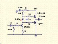
Rail Voltage 50VDC; Load 8 Ohms. Output Signal 1VAC 2kHz.
First version AMP:
Second Harmonic: 116 uV
Third Harmonic: 8.2 uV
Second Version AMP:
Second Harmonic: 4.6 uV
Third Harmonic: 11.5 uV
At 20kHz sinewave signal, same conditions:
First version AMP:
Second Harmonic: about 560 uV
Third Harmonic: about 500 uV
Second Version AMP:
Second Harmonic: about 30-40 uV
Third Harmonic: not measured.
----------------------------------
Other harmonics, are below noise level.
"uV" means "micro" Volts.
EDIT: in the second version output transistors are double die Laterals (ECW20N20, ECW20P20), in first version single- die.
Last edited:
Here's my take.......
A VERY articulate amp.
Very Nice Little AMP!!
But there is no Global NFB. THD and output impedance could be too high...
How much current is here for VAS?
Hi, are those values measured or simmed?
It's a nice little cute amp, especially the 2nd. 🙂
Edit: I found an amp design by Juma which is very similar to your 2nd version, see here:
25W Class A amp with Lateral MOSFETs
Last edited:
> But there is no Global NFB.
An advantage soundwise.
> THD and output impedance could be too high...
THD ~0.06 % @ ~ 6 Watts
Output Z ~ 1 Ohm.
> How much current is here for VAS?
22k Ohm driving fets
An advantage soundwise.
> THD and output impedance could be too high...
THD ~0.06 % @ ~ 6 Watts
Output Z ~ 1 Ohm.
> How much current is here for VAS?
22k Ohm driving fets
Hi, are those values measured or simmed?
It's a nice little cute amp, especially the 2nd. 🙂
Edit: I found an amp design by Juma which is very similar to your 2nd version, see here:
25W Class A amp with Lateral MOSFETs
Hi, thank You.
Yes, simmed.
Juma's AMP is good, but more complicated.
Historicaly it is the old idea, Rod Elliot was also described similar amp, BJT version with Bootstrap:
Simple 60 Watt Power Amplifier
I also simmed bootstraped version with Laterals, but there is only a little improvement in Harmonic Distortion, but not so good results, when AMP returns from clipping.
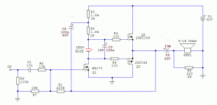
If we want it really simple (3 MOSFETs) and still nice sounding, with much lower output impedance and THD we can increase the OLG (by bootstrap loading the Q1) and introduce some feedback (R1/R2 ratio sets the gain).
R7 sets the output symmetry (50k trimm-pot can be used) i.e. half of the supply voltage at the Sources of the output MOSFETs.
If you want to change the gain lower the R1 value but then you'll have to change the R7 too.
Power supply voltage can be 30 - 60V DC.
Blue LED (Vf=3.5V) sets the output stage bias to about 0.8A. For lower output bias current green or red LED can be used (that will change the sound too).
Zin equals R2. Zout is less than 0R1.
Output power will depend on power supply voltage and the speaker's impedance. With 60V PS (tested with 400VA/~40V transformer) it will be about 40W into 8R.
EDIT: Now I see it's topologically similar to what Bruce@bluff proposed in post #26
Attachments
Last edited:
That's not important on this design level - upper bandwidth limit is dominantly determined by value of R2 and parasitic capacitance of Q1.
As I already said, there will be no asymmetry because the response to higher frequency signals is determined by R2/Q1 on a lower level, before the gates of output MOSFETs come into play. It's a simple circuit, you can cobble it up quickly and check it yourself.
Why shouldn't it be OK ? -3dB response is more than 100kHz and phase shift at 20kHz is about 5 degrees. What's wrong with that ?
Bs170 60pF is the input capacitance - when VDS is zero volts.
https://www.onsemi.com/pub/Collateral/BS170-D.PDF
When VDS is about 5-60V capacitance is about 35-30pF.
But here is another more complicated capacitance. It is output capacitance, it changes from 80pF to 17pF depending on VDS. And even more it has a Miller Effect, when gain is 20x, capacitance will be 1600 pF - 340 pF plus input capacitance 60...30pF.
It limits open loop gain at high frequencies and distortion at that frequencies will rise accordingly.
So worrying about very small problem:
It is not necessary 😉R4 and R5 should not be equal since gate capacitance of the two devices are different.
Of course there is a lot of room for improvements in all the designs in this thread. But, as the thread title says, it's about very simple and stable amps - not the best performing, just decent....
I built many of these and they work very well. I cant remember the name of the magazine it was featured in. I used 2sk1058 and 2sj162 and doubled up on the output and ran it from 80v supply
This AMP simulation (Supply 80VDC, bias same as mine AMP's, 1kHz, 1VAC Vout) shows:
H2 187 uV
H3 21 uV
Results without bootsrap (just omitted electrolyte cap).
With bootstrap simulation shows that it is a little bit prone to oscillation about 2 MHz. And harmonic analysis results are worse.
Attachments

- Status
- Not open for further replies.
- Home
- Amplifiers
- Solid State
- Very simple and very stable power AMP