Very simple Single Supply Lateral MOSFET amplifier
Hi,
this simple design offers:
* Very good PSRR;
* Very stable (unity gain stable), it could be connected after volume control pot - benefit - volume control also controls amount of negative feedback;
* Negative feedback (NFB) is 40 dB at 20 kHz at nominal gain of 25dB (some "audio" opamps does not offer such a good amount of NFB at this frequency, for example OPA2134 gain is 50dB at 20kHz, so when required gain is 25dB it has only 25dB left for NFB, thats why we see rising THD from 1kHz...);
* No compensation needed;
* Good linearity, also linearity increases at low listening levels (because of higher NFB);
* Capacitor at the output - no DC protection needed;
* Could work in CLASS A, or CLASS AB (R18 and R19 are variable resistors);
* Very small PCB (will be provided if asked);
Cons:
* Transistor Q5 should be very fast and very linear, i Used 2SC2910;
(CCS transistors are 2SA1208 and 2SB716);
* Output Mosfets should be Laterals, because there is no temperature stabilization.
* Not fast, Slew Rate is only 6.4V/us
Please feel free to build it if you like it - for non commercial purposes only 🙂
EDIT1: Here is the latest version of Single Ended VAS simple Amplifier:
Very simple and very stable power AMP - Page 7 - diyAudio
EDIT2: Here is the latest Complementary (push-pull) VAS version:
https://www.diyaudio.com/forums/solid-state/301486-simple-stable-power-amp-8.html#post5783587
Attachments

Last edited:
At last, a single supply mosfet amp! I like speaker caps for home builds without PWB. You mess up, you still have a speaker coil.
Thanks.
Output graph shows 20v out, so your supply V1 was maybe 50V?
For the less experienced, available lateral FETs are Alesis ALF08N16v and ALF08P16v also 20V, stocked at several places in the world by Farnell. N is nfet, P is pfet. datasheet on farnell website (newark in USA)
Thanks.
Output graph shows 20v out, so your supply V1 was maybe 50V?
For the less experienced, available lateral FETs are Alesis ALF08N16v and ALF08P16v also 20V, stocked at several places in the world by Farnell. N is nfet, P is pfet. datasheet on farnell website (newark in USA)
Also, Exicon ECX10N20/10P20 (from Profusion PLC) are the same parts as the ALFET types referred to and RENESAS 2SK1058/J162 (from a number of US sources) are near the same product too. No problem with local sources if you look around...... available lateral FETs are Alesis ALF08N16v and ALF08P16v also 20V, stocked at several places in the world by Farnell.
Guitar-man, have you perhaps been inspired of my Godzilla project that I nurtured here on Diyaudio some weeks ago?
Your design resembles of a mosfet version of that amp. Actually I'm about to build myself a mosfet prototype, I have just ordered some fake(?) IRFP240/9240 from China.
I can send you the schematics but I will not publish it here.
But my version will be more complex since I don't want any capacitor at the output and so that the signal ground will be at GND.
For me, this is the ultimate amplifier design. Short NFB path that ensures a THD of low "complexity", yet it doesn't distort any more than a complex one.
Svitjod, I have not seen Your project.
I was inspired by this:
Mini-MosFet Audio Amplifier - RED - Page123
But this "little" schematic had problems - The bias is very sensitive to power supply voltage - You need a regulated, very stable power supply. So I made some changes and tweaks.
Yes, NFB is as short as possible - only one amplifying stage in feedback loop.
Well it's just in my taste - elegant. I had never seen that topology until I "invented" it some time ago. At least to be used as serious hifi.
I'm sure it sounds fabulous.
My own BJT version does too.
I'm sure it sounds fabulous.
My own BJT version does too.
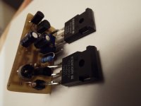
Only today I connected it and tested!
Worked from the first try and really stable.
B+ is about 47VDC
Bias Current 285 mA
Installed it instead of LM3875 single supply "Gainclone". Sounds noticeably better. Even better than I expected (because I had future plans to build same topology follower <BJT emitter follower loaded with BJT CCS + N and P-Laterals as complimentary followers> + tube VAS in front (maybe with no negative feedback).
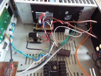
*No pops/oscillations during ON/OFF (I had problems and minimized them when used LM3875 - it oscillated/popped during ON/OFF)
*No annoying sound (digdig-digdig) when Cell phone is dealing/ringing event at 10cm distance from amplifier inputs. It starts "digging" when cell phone is about 1cm from the input.
*Future plans - lower supply voltage to 16-24VDC, then I will be able to adjust higher bias current (to be near class A operation) with not too hot heat-sink.
Worked from the first try and really stable.
B+ is about 47VDC
Bias Current 285 mA
Installed it instead of LM3875 single supply "Gainclone". Sounds noticeably better. Even better than I expected (because I had future plans to build same topology follower <BJT emitter follower loaded with BJT CCS + N and P-Laterals as complimentary followers> + tube VAS in front (maybe with no negative feedback).
*No pops/oscillations during ON/OFF (I had problems and minimized them when used LM3875 - it oscillated/popped during ON/OFF)
*No annoying sound (digdig-digdig) when Cell phone is dealing/ringing event at 10cm distance from amplifier inputs. It starts "digging" when cell phone is about 1cm from the input.
*Future plans - lower supply voltage to 16-24VDC, then I will be able to adjust higher bias current (to be near class A operation) with not too hot heat-sink.
Attachments
I suppose it only works perfectly at a certain supply voltage, as the center voltage is set by R17 and R18 (and the behaviour of Q5 and it's emitter resistor, of course).
Best regards!
Best regards!
I suppose it only works perfectly at a certain supply voltage, as the center voltage is set by R17 and R18 (and the behaviour of Q5 and it's emitter resistor, of course).
Best regards!
Yes, R18 it is a trimmer, sets the midpoint at output (B+/2).
R4 i left 0 Ohms (no need to degenerate emitter).
Slightly more complex example
Some of you might be interested in this slightly more complex design:
MJR7-Mk5 Mosfet Power Amplifier Design Notes
Some of you might be interested in this slightly more complex design:
MJR7-Mk5 Mosfet Power Amplifier Design Notes
Hi Guitar.mod,
Can you provide pcb layout?
Thanks,
http://www.diyaudio.com/forums/members/guitar-mod.html
Can you provide pcb layout?
Thanks,
http://www.diyaudio.com/forums/members/guitar-mod.html
Have You made it?
My Amplifier is still working as main amp - no faults... I think to make one more, that would change my SE ECL85 tube amp in the kitchen, because speaker's sensitivity is only 86-87 dB and I am starting to hear THD when listening a bit louder than 2 Watts of output power 🙂
My Amplifier is still working as main amp - no faults... I think to make one more, that would change my SE ECL85 tube amp in the kitchen, because speaker's sensitivity is only 86-87 dB and I am starting to hear THD when listening a bit louder than 2 Watts of output power 🙂
Nice design! I am a sucker for simple single rail supply amps. I have no qualms about using output caps. I have some 2SK1058 and 2SJ162 lying around unused. Could KSA1381 and KSC3503 and KSC1845, BC546C/557C or BC550C/560Cwork as that's what I have lots of on hand?
Nice design! I am a sucker for simple single rail supply amps. I have no qualms about using output caps. I have some 2SK1058 and 2SJ162 lying around unused. Could KSA1381 and KSC3503 and KSC1845, BC546C/557C or BC550C/560Cwork as that's what I have lots of on hand?
Thank You!
Use KSA1381/KSC3503 With suffix F or E.
Nice amplifier. I have built a version you have been inspired of. It was some time ago, but worked nice and fine. Now this version with Laterals is also interesting, especially when you compare ECL85 with it. I use ECL82 as main amp. Can anyone beat it? Maybe Laterals. How much output you get?
Hi Mindutis,
thank You. I get about 23W of output into 8R.
thank You. I get about 23W of output into 8R.
ECL82 SE - Could be beated by many higher output amps, if You need slightly higher Output and lower THD as in my case 🙂I use ECL82 as main amp. Can anyone beat it?
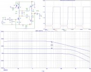
Here is an update to the schematic: faster, slightly better THD, higher input Z, even more simple - and no annoying trimmers for setting up the Amplifier at all!
At the Upper right corner it is clipped 20kHz sine wave at the output.
At the Upper right corner it is clipped 20kHz sine wave at the output.
Attachments
Last edited:
- Status
- Not open for further replies.
- Home
- Amplifiers
- Solid State
- Very simple and very stable power AMP