I am fascinated by simple, so yesterday I had a few hours to experiment with this little fellas:
http://tinyurl.com/y7v99ccn
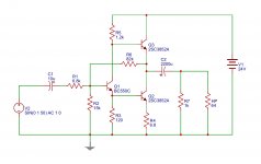
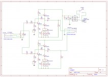
I used BC550C and and the 2SC3852 because I had them around. Love them both for their role, cheap and performing.
I was also looking for high Hfe for power NPNs there, and the 2SC are plenty.
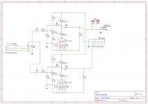
The amp has an input impedance of about 12K Ohm and a gain of about 3.5.
It is fed with 24V DC as I had a power brick around to spare. Final build will also likely use it.
The BC550C is biased at about 8.6mA, while the output stage varies according to the emitter resistor value of the lower NPN (from 40mA to 80mA).
In order to achieve the best performance, the value of that resistor should be somehow dependent on the headphone impedance.
In/Around 1/7...1/8 times that, to be more precise.
A too high value can lead to the lower NPN not being able to drive enough current in the negative side of the waveform, and a value too low will make the lower NPN to over-conduct by increasing dissipation power of the higher NPN.
I am likely going to use a 2P4T switch there, to select different resistor values.
For standard biasing values, there should be no need of heatsinks for the 2SC3852.
The 1K Ohm resistor is there to provide a discharge path for the output coupling capacitor.
The advantage of this circuit over the usual class A, lower current source, design is that this requires much lower biasing current (1/4 to 1/8), and has a much softer clipping behavior.
Power wise, it can deliver more then 1W on 32 Ohms loads, and about 100mW on 500 Ohms loads.
PS: Sorry for the interactive circuit link ... have not had the time to port it to Kicad and export and image file yet.
http://tinyurl.com/y7v99ccn
I used BC550C and and the 2SC3852 because I had them around. Love them both for their role, cheap and performing.
I was also looking for high Hfe for power NPNs there, and the 2SC are plenty.
The amp has an input impedance of about 12K Ohm and a gain of about 3.5.
It is fed with 24V DC as I had a power brick around to spare. Final build will also likely use it.
The BC550C is biased at about 8.6mA, while the output stage varies according to the emitter resistor value of the lower NPN (from 40mA to 80mA).
In order to achieve the best performance, the value of that resistor should be somehow dependent on the headphone impedance.
In/Around 1/7...1/8 times that, to be more precise.
A too high value can lead to the lower NPN not being able to drive enough current in the negative side of the waveform, and a value too low will make the lower NPN to over-conduct by increasing dissipation power of the higher NPN.
I am likely going to use a 2P4T switch there, to select different resistor values.
For standard biasing values, there should be no need of heatsinks for the 2SC3852.
The 1K Ohm resistor is there to provide a discharge path for the output coupling capacitor.
The advantage of this circuit over the usual class A, lower current source, design is that this requires much lower biasing current (1/4 to 1/8), and has a much softer clipping behavior.
Power wise, it can deliver more then 1W on 32 Ohms loads, and about 100mW on 500 Ohms loads.
PS: Sorry for the interactive circuit link ... have not had the time to port it to Kicad and export and image file yet.
Last edited:
Free time on turkey holiday ... 
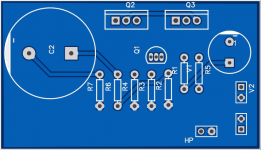
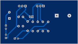
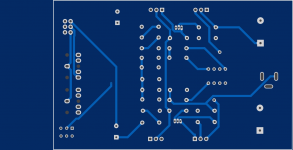
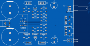
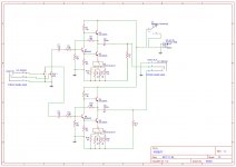
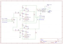
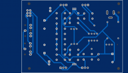
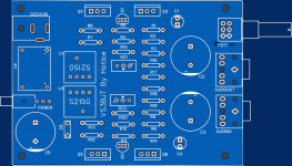
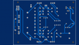
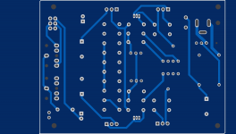
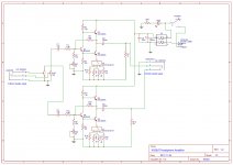
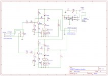
Here's a new version which adds some missing pieces and emitter resistor selection.
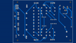
EasyEDA routing is not stellar, and I like no vias, so I spoiled myself with a 4 layers.
Here's a new version which adds some missing pieces and emitter resistor selection.
EasyEDA routing is not stellar, and I like no vias, so I spoiled myself with a 4 layers.
Attachments
Last edited:
Thanks AKSA!
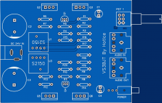
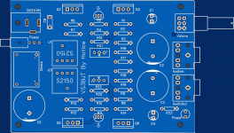
One more round. Added choke filter to lower ripple from 24V supply, and included full Digikey bound BOM.
One more round. Added choke filter to lower ripple from 24V supply, and included full Digikey bound BOM.
Attachments
I think it's close to done.
Added precision trimmer to allow tuning the center voltage, and few other touches.
Added precision trimmer to allow tuning the center voltage, and few other touches.
Attachments
Argh, thanks! I owe you $50!
The emitter resistor regulates the amount of pull on the negative side of the output signal.
Consider the old variations of similar circuitry, WRT the low side of the output stage.
The first one you have a class A bias with a relatively small resistor.
With that setup you have large dissipation on the resistor, a class A bias (heat) and a lame pull on the negative side of the output signal. Essentially, your output impedance on the negative side is the resistor value you sink the class A current through.
The second one is a constant current generator, which requires again a class A bias, which also has a bad clipping behavior once you run out of current.
With this configuration you have an active pull on the negative side of the signal, which is essentially dVin/Re.
But if Re is too small for the HP load, you sink that current through the upper NPN, which means more heat for it.
You can play with the simulation, changing HP load and Re, an notice the upper NPN current/voltage behavior.
Attachments
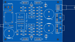
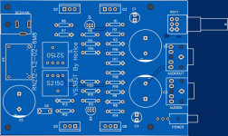
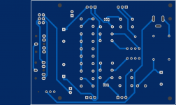
OK, should be ready to send Gerbers to manufacturing.
It was missing an LED, and it is no amplifier if it does not have an LED (strictly blue!)
For this I was not thinking of any enclosed case, but more sandwiched among two 1/4" clear acrylic panels, held with brass PCB standoffs.
New simulink here with updated Hfe:
http://tinyurl.com/ycyxpnqg
The models used by that simulation are much less sophisticated than spice (I use ngspice) ones, but I usually have not found much of a difference once compared them, especially for such static analysis.
Overall, as experiment of a project done 100% with an online EDA tool, it turned out that for simple stuff like this, I can work with it.
Though some times I felt missing KiCad
Attachments
Member
Joined 2009
Paid Member
Nice !
another idea - maybe add a small cap from base of input transistor to ground, a small npo ceramic, which in conjunction with the input resistor makes an RC filter for pesky r.f. leaking in from the local radio station.
why did you choose to have the wiper of the volume pot to the source ? when volume is dialled to zero it will place a near-short on the source ? I usually put the wiper of the pot to the base of the input transistor ?
Thanks!
I think many BJTs will work.
I just chose those because I had them around. They both have very nice performance for the price (they 2SC are $1.5 IIRC at Digikey).
They tend to dissipate (depending on emitter resistor choice) from 600mW to 900mW, so they should be fine w/out heatsink (they will be pretty hot to touch).
I would not call this class A. More class W (for Weird ).
If you open the simulation, you notice the audio output has about +/- 7.5V swing (using a 2V input), and delivering +/- 150mA on a 50 Ohms load.
A class A will have to be biased to 150mA at least, to not have the signal chopped.
Now right click the signal source, Edit, and set voltage to 0 (DC simulation).
You will notice a 50mA bias current, about 1/3 of a class A.
I think many BJTs will work.
I just chose those because I had them around. They both have very nice performance for the price (they 2SC are $1.5 IIRC at Digikey).
They tend to dissipate (depending on emitter resistor choice) from 600mW to 900mW, so they should be fine w/out heatsink (they will be pretty hot to touch).
I would not call this class A. More class W (for Weird
).If you open the simulation, you notice the audio output has about +/- 7.5V swing (using a 2V input), and delivering +/- 150mA on a 50 Ohms load.
A class A will have to be biased to 150mA at least, to not have the signal chopped.
Now right click the signal source, Edit, and set voltage to 0 (DC simulation).
You will notice a 50mA bias current, about 1/3 of a class A.
Duh!Nice !
another idea - maybe add a small cap from base of input transistor to ground, a small npo ceramic, which in conjunction with the input resistor makes an RC filter for pesky r.f. leaking in from the local radio station.
why did you choose to have the wiper of the volume pot to the source ? when volume is dialled to zero it will place a near-short on the source ? I usually put the wiper of the pot to the base of the input transistor ?
Another $50 saved (I was bout to submit the PCB order
).Thanks!
Yeah, does not make ANY sense ... totally missed that when I change from the ALPS to the Bourns POT.
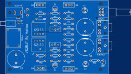
PCB and components should be here next week
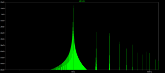
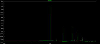
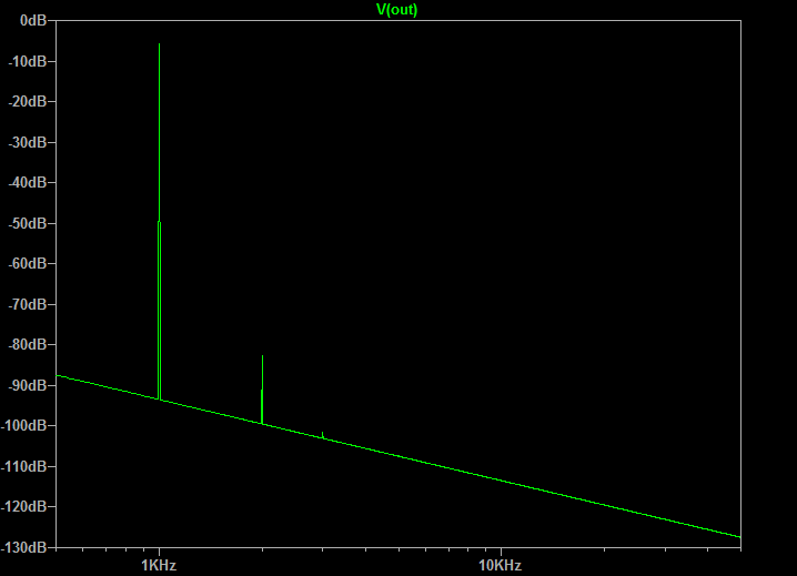
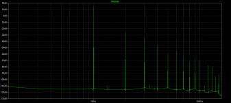
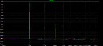
Here are the FFTs of emitting 16V and 4V peak-to-peak on a 30 Ohms load.
Not too bad considering in the first case we are dumping about 1W RMS, and considering the pretty low NFB value.
Here are the FFTs of emitting 16V and 4V peak-to-peak on a 30 Ohms load.
Not too bad considering in the first case we are dumping about 1W RMS, and considering the pretty low NFB value.
Attachments
- Status
- This old topic is closed. If you want to reopen this topic, contact a moderator using the "Report Post" button.
- Home
- Amplifiers
- Headphone Systems
- Very Simple 3BJT Headphone Amplifier