Hi all,
I have been searching the forum for wisdom on designing an output stage that does not favor maximizing wattage, but understandably there are many more threads dedicating to squeezing the most out of each tube. Several years ago I built an Aikido preamp with 6sn7s and provided them with a generous PS. I wondered the other day if I could use that unused B+ to supply an unimposing pair of output tubes. The transformer HV secondary is rated for 150mA and the 4 preamp tubes use around 40mA all together. Would it be possible or advised to fit a pair of, say, 6l6s in there so they draw no more than 40mA each and still sound good? The Aikido provides a lot of voltage gain, I have efficient speakers, and I plan to listen at modest volumes near by. I love the idea of adding an output stage for the price of 2 tubes, OPTs, and a handful of small components. Am I dreaming? If not, what tubes should I consider, and are there any simple schematics that lend themselves to this objective?
Thanks for your suggestions.
We need to know how much current your power supply is capable of delivering to the amplifier and not just the transformer. For instance if you are using a full wave rectifier and a capacitor input, then you would be getting the full 150ma of current capacity of the transformer. However, if you are using a full bridge rectifier and a capacitor input, you would only be getting ~62% of 150ma which would only leave you with ~93ma of current capacity.
Please refer to this chart to figure how much DC current you can supply to the amplifier.
http://www.hammondmfg.com/pdf/5c007.pdf
Please refer to this chart to figure how much DC current you can supply to the amplifier.
http://www.hammondmfg.com/pdf/5c007.pdf
Do you have enough headroom in heater current, or are you willing to add a heater transformer? Say, 2 Amps? If so, you might begin by considering a single-ended triode output single stage with a mu of 10 to 20, something in the 6V6 family or EL84s.
This is guessing that your raw B+ is in the 250 - 300 VDC range. If it's appreciably more, you'll really want a bigger valve, which tend to come in the mu = 8 family, 6L6, etc. and need a driver stage. If appreciably less B+, then maybe a 6BM8 or similar. All of these choices will work well with 5K Ohm output transformers.
All good fortune,
Chris
Short answer is yes, you can do that. Assuming you have the transformer power avialable, you can always run big bottles as cool as you like. Triode mode, cathode bias, simple as you like. Although if you want to stay in class A then it might be easier to use something a bit smaller, like 6V6 or whatever.Would it be possible or advised to fit a pair of, say, 6l6s in there so they draw no more than 40mA each and still sound good?
Very low wattage, you say. If 1 WPC is enough, JJ's ECC99 will take care of both channels, in a single bottle.
At 5 Watt maximum rating per ECC99 Anode . . .
getting 1 Watt out of the output transformer (OPT) is possible if it has low insertion loss.
At 25% SE efficiency, 5 Watts = 1.25 Watts to the output transformer.
An inexpensive OPT that has 1 dB insertion loss . . . 1.25 Watts in, 1 Watt out.
Squeeze more out, but it will be fairly high distortion.
That amplifier will have those Anodes near to the 5 Watt maximum.
I believe the original post mentioned using an output tube well below its maximum rating.
EL84 filament 0.74A
7591 filament 0.8A
6V6 filament 0.45A or 0.5A
6L6 filament 0.9A
These all are possible candidates (and have at least 12 Watt maximum plate dissipation specs).
All can be run in Ultra Linear or Triode wired mode (or in Beam Power mode).
Last edited:
Is the spud acceptable?
1:2 ... 1:4 SUT, E55L tube, cathode resistor // capacitor, OPT, PSU: 1.5..2W .
1:2 ... 1:4 SUT, E55L tube, cathode resistor // capacitor, OPT, PSU: 1.5..2W .
thank you all for the thoughtful replies, I am trying to make sense of it all. To start with the missing info, attached is a schematic of the PS modeled in PSUII. I should add that the voltage and current figures I measure are different than predicted, for instance the voltage at the C5 is 330-335V, not 280V, which is pretty high for the preamp tubes. The transformer is the Hammond 272FX, 600V c.t. at 150mA with 5V at 3A and 6.3V at 5A. Regarding the filaments, I have an 8V transformer supplying a regulated DC supply, so filament current is not a problem. I have several questions based on your comments but I will try to get up to speed first.
Attachments
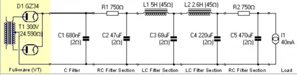
Tjj226 supplied a reference for recalculating Dc current capacity depending on transformer, rectifier, and filter type. For LC and full wave application it seems that this is measured after the choke and I might enjoy an additional 50%, or 75mA. If we ptovide for 20% headroom, that is around 175mA, less the 4 preamp tubes that leaves 135mA. Maybe I should retitle the post “low but lets be reasonable wattage power stage question.”…?
Not certain that I'm following you. Are your existing chokes rated for 150mA? Or are you intending to add other chokes for the power amp? The existing supply is not choke input, so the transformer's current rating is still 150mA. With extra load, you could expect B+ in the 300 VDC range - very flexible - and slightly more than 100mA (to spare).
Only the highest mu valves will be sensitive enough to let you get away without a driver stage, but it can be done, given your stated requirements for work/library/study use (my interpretation!). The magic number here is the EL84, but if you're high speed low drag you might consider the 7591 into a 3K to 5K Ohm load. Or accept a driver stage, and you can use 6L6 class valves, 5K Ohm load. All triode connected of course.
One issue to consider is the grounding strategy, but this has all been done before, and in fact was very common in the early days. Output amplifier and power supply on one chassis, umbilical to preamp on a remote chassis. Can be done.
All good fortune,
Chris
Last edited:
Hi Chris,
I must misunderstand the concept here. I am looking at the attached diagram. The xformer is rated for 150 mA Ac, the 5H choke in my PS is rated for 200mA and the 2.6H at 300mA. I was (wishfully) thinking that I might get more than 150 mA in Dc current after the filter section…no? And I hear you that getting a power section with whatever current is left over is possible, so we are in business. And your assumption about my listening environment is totally correct, furthermore, my wife will often be present so less is more so to speak. Also, if the OPTs are not too big, it is possible to squeeze everything into the same chassis, which is pretty big.
I must misunderstand the concept here. I am looking at the attached diagram. The xformer is rated for 150 mA Ac, the 5H choke in my PS is rated for 200mA and the 2.6H at 300mA. I was (wishfully) thinking that I might get more than 150 mA in Dc current after the filter section…no? And I hear you that getting a power section with whatever current is left over is possible, so we are in business. And your assumption about my listening environment is totally correct, furthermore, my wife will often be present so less is more so to speak. Also, if the OPTs are not too big, it is possible to squeeze everything into the same chassis, which is pretty big.
Attachments
Last edited:
Now I understand - you're intending to convert to choke input, and keep the existing chokes and accept a lower B+ to the preamp. The existing large 750R resistor will have to go anyway, so you can expect - what?, about 250 VDC and lots of current. Call it preamp draw of 40mA plus another 120mA plus. 5 Hy is comfortably above critical for current drain of more than 80mA, and you're good to go.
That's enough to do push-pull, with driver/phase splitter and all, if you wanted to. Or a very warm biased 12 Watt EL84 or 6V6 or the lovely 6pi1pi from Svetlana St. Petersburg from the late 1960s that are available for probably not much longer, single-ended with a 6SN7 driver. Or 6L6.
All good fortune,
Chris
Last edited:
The reason I added those 750 Ohm resistors was to get the voltage down. Previously I had a single 300 Ohm resistor in the last RC section and my B+ was over 390 vdc. I’m guessing the 6sn7s won’t last long up there. The current PSD II modeled PS above was projected to level off at 280V. What would you recommend changing in the current PS to lower the voltage, increase available current, and maintain <1uv ripple?
Last edited:
Now I understand - you're intending to convert to choke input, and keep the existing chokes and accept a lower B+ to the preamp. The existing large 750R resistor will have to go anyway, so you can expect - what?, about 250 VDC and lots of current. Call it preamp draw of 40mA plus another 120mA plus. 5 Hy is comfortably above critical for current drain of more than 80mA, and you're good to go.
That's enough to do push-pull, with driver/phase splitter and all, if you wanted to. Or a very warm biased 12 Watt EL84 or 6V6 or the lovely 6pi1pi from Svetlana St. Petersburg from the late 1960s that are available for probably not much longer, single-ended with a 6SN7 driver. Or 6L6.
All good fortune,
Chris
With a choke input he would only get ~135v assuming no loss.
-----------
I am looking at the OP a bit more carefully now. For the aikido preamp tubes to be drawing 40ma, each tube would have to be biased at 10ma. That is a pretty hot bias for a 6sn7 and would recommend reducing the bias.
I honestly think the bias is probably closer to 5ma which would make the total current draw from the preamp only 20ma.
This would mean that if the OP sticks to using a full wave rectifier with a capacitor input, he will have the full 150ma of current capacity minus 20ma which would leave him with 130ma of current capacity.
With 130ma of current, you definitely have some options. I would still probably try to be a bit conservative with your choice of tubes. While something like a 300b is possible, I would be concerned about the power supply sagging when you try to play a large transient. But, I would get someone else's opinion on that first.
Somewhere above he said 600 VACct, so 270 VDC choke input assuming no loss. What would we really get? Maybe 225 - 240 VDC? Assuming the 750R dropping resistors are gone too.
That seems really low to me for 6SN7s stacked vertically for DC - something in the 300 - 400 VDC range would be my entirely personal choice. The 10mA bias is on the high side of conventional, but would be very linear within its voltage swing abilities, and within dissipation limits. I'd probably have gone lower, but it's a bold move and interesting.
An option seldom explored (or often overlooked?) is to use both choke input, for the output stage, and capacitor input, for the upstream driving stages. Build a choke input supply appropriate for the output stage, and add a 1N4007 diode from the rectifier - first choke junction to a capacitor input filter for the driving stages. Extra parts, but they're all in the power supply. Optimized voltages for each stage from a single power transformer and GZ34, and better isolation between. Costs more, of course.
All good fortune,
Chris
Thanks for the replies; let me clear up, but likely muddle things up a bit more...Yes, it is a 300-0-300 V secondary. I get the 40mA current draw from the 4 6sn7 tubes after 5 minutes warm up with my DMM in series between PS and B+ in on board. I am supplying a 500mV 1k sine wave to the tubes but no load.Was the 5mA bias referring to per tube or per triode? If the latter then, yes, although the input tubes and output tubes are not biased equally.
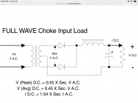
I am still missing something about the choke input load. Correct my mistake: I was thinking that DC current has a gain of x1 with and RC stage on the secondary, and a 1.54 DC current gain with choke on secondary. Shouldn't that be 1 x 1.5 which equals...225mA DC?
Just to review ideal design goals:
1. Aikido gets to do it's thing without competing with a guitar amp output stage
2. I hope to listen at a level close to the SPL of my speakers, which have 89.5 SPL, so 1 watt or less will do.
3. Avoid the additional $200+ cost of extra iron and caps in PS
Thanks again
Last edited:
- Home
- Amplifiers
- Tubes / Valves
- very low wattage power stage question