diynewb83, your psu sim relates to a perturbation on the rectifier side of the filter, without a load on B+, and without the stiff voltage source connection periodically connecting to C5 when the diodes conduct. I suggest that sim does not convey any practical information for what is happening on the B+ side of the filter for your B+ side perturbations.
diynewb83, your psu sim relates to a perturbation on the rectifier side of the filter, without a load on B+, and without the stiff voltage source connection periodically connecting to C5 when the diodes conduct. I suggest that sim does not convey any practical information for what is happening on the B+ side of the filter for your B+ side perturbations.
You are correct, I did not put the rectifier in the circuit, oops. That would explain the micro-ripples(60Hz) in the wave. B+ is under load in the sim, I just did not re-paste the entire schematic shown in the first post.
Even with a solid 457Vdc source this motorboating is occurring in the sim.
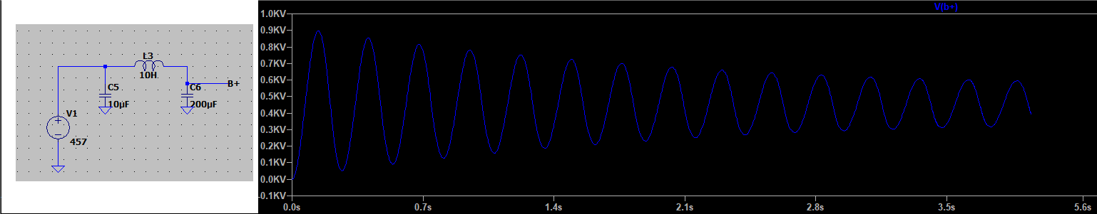
Excitation of any pure LC circuit will result in oscillation. Any real circuit will have losses - in this case, the load on the supply. How fast does it damp out with say a 100mA load? Try loading in 5k ohms, and re-run your simulation.
Excitation of any pure LC circuit will result in oscillation. Any real circuit will have losses - in this case, the load on the supply. How fast does it damp out with say a 100mA load? Try loading in 5k ohms, and re-run your simulation.
Yes, and it's clear to me now where these oscillations are coming from. I have nothing to dampen them. I'm already working on a series of RC filters to decouple the stages into their own HT lines and smooth it out. In the real circuit, I think the global feedback I had made it much worse, but I saw without it is was still there if I looked closer.
To answer your question directly, not very fast. I tried it even at 200mA via 2.5k in the sim, and even 5 seconds out(obviously still a perfect circuit) it's still ringing.
Right now I'm trying to work out the proper RC values and sending a pulse through the input a few seconds after it stabilizes to see how bad each one rings.
i didn't look at your original topicbefore but now it's absolutely clear that you need to lower the values of those 220nf coupling capacitors...make them 5....20 times smaller.
Yep you have two many poles in your feedback - two sets of coupling caps and transformer. If they are all about the same break frequency then you will have >180deg phase shift as the loop gain goes through unity - oscillator. There are a number of ways of solving have a good read of LF stability in amps. Reducing the number of poles, making one pole dominate over the rest and lead-lag compensation. Making one pole dominate means making one and only one of the coupling caps smaller so it starts to roll off and brings the gain to below unity before the pole of the transformer other cap kicks in. You need to break the loop and do a bode plot in LTspice (quite easy).
Last edited:
I had some time to build out some RCs on the PSU prototype to decouple the stages and the problem has gone away entirely, not even a hint of it. I'm able to get the frequency response and power I want.
Now onto the next problem, which I think is just blocking distortion - very occasionally a "kick"(as in the drum) is missing when playing at high volumes. I think using the much smaller coupling caps as suggested may help with that.
Thanks everyone again for your input.
Now onto the next problem, which I think is just blocking distortion - very occasionally a "kick"(as in the drum) is missing when playing at high volumes. I think using the much smaller coupling caps as suggested may help with that.
Thanks everyone again for your input.

Here, there are two RC couplings, one with a cutoff of 18.1 rad/sec and 4.1 rad/sec. These are too close, being just a bit over two octaves. These should be staggered by a decade to keep the phase shifts from piling up to cause excessive end-to-end phase shift. These cutoff frequencies are much too low.
To answer your question directly, not very fast. I tried it even at 200mA via 2.5k in the sim, and even 5 seconds out(obviously still a perfect circuit) it's still ringing.. Right now I'm trying to work out the proper RC values and sending a pulse through the input a few seconds after it stabilizes to see how bad each one rings.
Don't worry about ringing in the ripple filter. The only difference between an LPF and a tuner is the Q-Factor. You could make a proper Butterworth ripple filter, but the values for the capacitors and inductors would become difficult to accomplish (small C, large L). More practical values will give Q-Factors greater than unity. You only have to prevent "filter bounce" when the ripple filter gets hit with pulses close to its resonant frequency. Back in "the day" that was more of a problem since high voltage/high capacitance electrolytics weren't available. Given the 10H choke and the 220uF capacitor w0= 3.39Hz -- yet another reason for getting the RC turnovers well above subsonic frequencies.
It's an oscillation if you are not inputting anything to the amp. It's ringing if it is associated with a waveform of some sort.
Try reducing the size of the coupling caps C2 and C4, and use different C values for them.
Try reducing the size of the coupling caps C2 and C4, and use different C values for them.
What does LTSpice show for frequency response? Accuracy depends on the quality of the opt model but it should still provide insight into the circuit's response to value changes.
Here, there are two RC couplings, one with a cutoff of 18.1 rad/sec and 4.1 rad/sec. These are too close, being just a bit over two octaves. These should be staggered by a decade to keep the phase shifts from piling up to cause excessive end-to-end phase shift. These cutoff frequencies are much too low.
Thanks Miles. Would you mind pointing out what resistances/assumptions(if any) were included in coming up with those cutoffs? I'm still learning all of the math, and in particular, what components are involved in it. Working backward(and assuming you only used the 220nF for capacitance) I'm getting ~251kOhm for the resistance on the 18.1 rad/sec and ~1.108MOhm on the 4.1 rad/sec. Obviously R2(220k) and R3(1M) are involved in there, but I'm having trouble following the subtle differences.
I have a ton of assorted caps coming in in a few days, so I can't wait to tweak it some more.
Thanks again.
What does LTSpice show for frequency response? Accuracy depends on the quality of the opt model but it should still provide insight into the circuit's response to value changes.
I believe I posted the frequency response on this thread, but when I switched it to 22nF instead of 220nF on C4 and C2, the low end spike was a lot more subdued(wider Q maxing at 28dB compared to sharp spike maxing at 38dB).
From my experience, my OPT model is close "enough" for LTSpice, but not even close to the real deal. After decoupling the stages, my original problem disappeared. I'll be working with the lower value caps when they come in. 220nF is all I had laying around, wasn't a real design decision, but I can see why that was a nutso choice to stick with.
I'll check out frequency response on the scope with the new caps.
- Home
- Amplifiers
- Tubes / Valves
- Very low frequency ringing