I've been looking at the datasheets for some of the earlier TDA20xx audio ICs. This is specifically about the old TDA2002. The feedback network in the sample circuit uses unusually low resistor values, namely 220Ω + 2.2Ω coupled to the inverting input by a large (470µF) capacitor. Why not, for example, 2.2k, 22Ω, 47µF or some other corresponding values?
The only thing I can think of is that they must want a very low impedance from the inverting input to ground but, looking at the internal diagram, I can't see any obvious reason.
Any thoughts?

The only thing I can think of is that they must want a very low impedance from the inverting input to ground but, looking at the internal diagram, I can't see any obvious reason.
Any thoughts?
Attachments
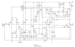
That's straight from the data sheet:

Lower resistance values would result in lower noise, but burning 360 mW in the feedback network at idle seems a bit wasteful. Also 40 dB is quite high gain.
It could be that the feedback network is intended to provide the TDA2002 with a minimum load current to ensure stability or something.
The data sheet makes no mention of a minimum gain and there's no AVOL curve, so I would proceed with caution when lowering the gain.
Tom
The question is: are such integrated ones still available for purchase somewhere? As far as I know, it has not been manufactured for a long time. Even from old stocks, it is still not worth designing a scheme that uses obsolete integrated.
It's still available and could be just right for some application. But that's not the point. This is purely a technical question.
It's always good to know why some things are done in a particular way. The knowledge might come in handy at some point in the future. I've analyzed countless numbers of circuits that I have no intention of using in practice.
It's always good to know why some things are done in a particular way. The knowledge might come in handy at some point in the future. I've analyzed countless numbers of circuits that I have no intention of using in practice.
The inherent shunt capacitance across the 220R is much less relevant than if R1 were 22k, for example.
Here is an excerpt from the data sheet (this is actually for the TDA2003, but it's the same for the 2002):

SVR = supply voltage rejection
SVR is not really great to start with (36 dB) so I would not degrade it further, unless you have a very clean supply.
SVR = supply voltage rejection
SVR is not really great to start with (36 dB) so I would not degrade it further, unless you have a very clean supply.
The inverting input is the emitter of a singleton input stage, not unlike a CFA. That usually wants a low impedance for best overall performance.
Another reason that is often overlooked is in the application space. These were used as car radio power amplifiers. Often, one would want more power than a typical head unit and try to use a booster amplifier connected to the speaker output because it was the only output available. That 220 ohms to ground forces the power amp chip to operate single ended CLASS A for load impedances > 220 ohms. This is very much like the crossover distortion fix for the LM358. Do not discount how much of a difference this makes. Most of these chips are pretty poor for crossover distortion natively, even at low loading.
Another reason that is often overlooked is in the application space. These were used as car radio power amplifiers. Often, one would want more power than a typical head unit and try to use a booster amplifier connected to the speaker output because it was the only output available. That 220 ohms to ground forces the power amp chip to operate single ended CLASS A for load impedances > 220 ohms. This is very much like the crossover distortion fix for the LM358. Do not discount how much of a difference this makes. Most of these chips are pretty poor for crossover distortion natively, even at low loading.
The inverting input is the emitter of a singleton input stage, not unlike a CFA. That usually wants a low impedance for best overall performance.
True for the TDA2003, not for TDA2002. TDA2003 does indeed look like a CFA but TDA2002 has a symmetric (LTP) input stage albeit with some internal biassing.
I always thought TDA2002 was a CFA because the old LM383 was, and so were TDA2003-5.
I have had less trouble with 2003 oscillating than 2002….. maybe that should have been a clue.
But you do get a factor of 10 improvement in crossover distortion when using any of them as a “preamp” if you hang 100 or 200 ohms to ground and let it bleed current. Worked a treat on my other favorite from the day, the Toshiba TA7205, too. When using one as a “preamp” it ends up being run at just the wrong output level to get the worst of it.

Sounds like a design oversight to me. Someone forgot to simulate the PSRR and the applications engineer came up with a solution. Not the first time that's happened and it won't be the last. 🙂SVR = supply voltage rejection
SVR is not really great to start with (36 dB) so I would not degrade it further, unless you have a very clean supply.
Tom
PSRR is always a challenge on single supply amplifiers unless an external ripple filter capacitor is used in the bias network. Some ICs have this pinned out. 5 pin packages kind of limit you a bit.
- Home
- Amplifiers
- Chip Amps
- Very low feedback resistor values with TDA2002