I've a problem regarding to my new pre-amp. My pre-amp is using 2 6072 EH tubes and the problem is how can I lower the output level? The output sound is very high, I just can only turn the volume control to around 8 o'clock and the output sound is already very high. I hope that you guys and help ,e to solve this problem. Thanks
A question to ask is, for what main amp sensitivity was your preamp intended? Is it compatible with your amp? If, for example, you have a Leak or Mullard-designed main amp, then the chances are that the output signal of most preamps would be much too high.
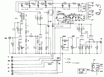
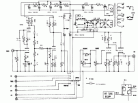
There's an inverting gain stage as a line amp. I can't read the numbers on the schematic too well, but it looks like you've got a cathode resistance of roughly 1K. 125K on the plate. With a plate resistance of 25K and a mu of 44, the effective plate resistance is about 70K. So the gain will be something like 27-30. That's about 29dB, a lot of gain.
You can go two routes: easy and non-optimal, or hard but optimal. The former way, just pad down the input. The latter, redesign the stage for much less gain, a non-trivial project.
You can go two routes: easy and non-optimal, or hard but optimal. The former way, just pad down the input. The latter, redesign the stage for much less gain, a non-trivial project.
You can always connect the grid of the cathode follower output stage directly to the volume control and eliminate the gain stage.
Nope, it's not that simple. If you do that, the DC conditions for the CF will be unsatisfactory. Conceptually, it's a fine idea, but implementing it will involve putting a DC bias string and a coupling cap at the input of the CF. That's not horribly difficult, but it will take some design effort to do it right.
SY said:Nope, it's not that simple. If you do that, the DC conditions for the CF will be unsatisfactory. Conceptually, it's a fine idea, but implementing it will involve putting a DC bias string and a coupling cap at the input of the CF. That's not horribly difficult, but it will take some design effort to do it right.
Why not just change the value of the cathode resistor?
No cap needed on the grid.
That's exactly the sort of thing that has given cathode followers a bad reputation. Drop that resistor and the distortion goes sky high. The drive capability goes away, too.
To do a proper cathode follower, you need some room under that cathode. Big resistor with a lot of drop or a current source with sufficient compliance. That means cap coupling and biasing up the grid or putting in a negative rail and running a resistor or current source to it.
Nontrivial.
To do a proper cathode follower, you need some room under that cathode. Big resistor with a lot of drop or a current source with sufficient compliance. That means cap coupling and biasing up the grid or putting in a negative rail and running a resistor or current source to it.
Nontrivial.
"Drop that resistor and the distortion goes sky high. The drive capability goes away, too."
Good point about distortion. Drive capability isn't an issue, however. The preamp is already overdriving the power amp.
How about some NFB from cathode to cathode?
Good point about distortion. Drive capability isn't an issue, however. The preamp is already overdriving the power amp.
How about some NFB from cathode to cathode?
Feedback is a good option, but will not be trivial to implement and (most importantly) stabilize. It can be done cathode-to-cathode, and best by tapping the CF load resistor and returning the first stage to that point.
The CF has the advantage of being noninverting and relatively easy to make stable.
The CF has the advantage of being noninverting and relatively easy to make stable.
- Status
- Not open for further replies.
- Home
- Amplifiers
- Tubes / Valves
- Very high output level!

