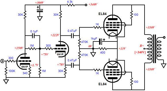
Hello. I am quite new to tube amps. I am building a small guitar amp with EL84 in push-pull configuration. I am using this schematic below. But when I was scrolling down the forums, I found, that power dissapation of each tube is 12W, so for that one cathode 400R resistor, it is 24W 😱. But where can I get sucha resistor, even if there are any?
So, my question is: Is it really necessary to put a 25W or 30W resistor here, or is my statement false? Because I think that for something like this 30W is a lot. I know, that AB amps require like 70% of max dissapation, but it's still a lot.
Thanks for any answers, would help me a lot 😀
So, my question is: Is it really necessary to put a 25W or 30W resistor here, or is my statement false? Because I think that for something like this 30W is a lot. I know, that AB amps require like 70% of max dissapation, but it's still a lot.
Thanks for any answers, would help me a lot 😀
Most designs would use a 400R 5W wire wound resistor. Don't know your country but this will give you an idea.
Through Hole Fixed Resistors
Alternately 390R is the preferred value.
The decoupling 1000uF capacitor is the wrong value. No higher than 220uF should be used to avoid saturation issues in the output transformer.
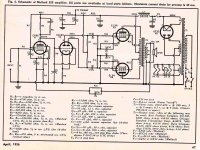
Attached is a proper design with information on the required values for EL34. EL84 is just half the power. If you look at the cathode resistor, there are two used, if you use one, a 390R is preferred at 5Watts if possible for reliability.
No need for anything higher as Kerckhoffs's Law if about current through components, not Watts.
Through Hole Fixed Resistors
Alternately 390R is the preferred value.
The decoupling 1000uF capacitor is the wrong value. No higher than 220uF should be used to avoid saturation issues in the output transformer.
Attached is a proper design with information on the required values for EL34. EL84 is just half the power. If you look at the cathode resistor, there are two used, if you use one, a 390R is preferred at 5Watts if possible for reliability.
No need for anything higher as Kerckhoffs's Law if about current through components, not Watts.
Attachments
Last edited:
Thanks. This would really move me forward, because this is that kind of information, that you only can get from more experienced person. I was scared putting those gigantic resistors in my circuits.
If you take the schematic at face value, the cathodes are at 13V. Ohms law tells you that the total current through the 400 ohm resistor is 13/400 = 32.5 mA (16.25 mA per tube). Power dissipated by the resistor is 32.5 mA x 13V = 422.5 mW. Normally you would use a resistor of at least 3 x power rating to avoid it getting too hot. 5 watt resistors are cheap and readily available so would be a reasonable choice.
Looking again at your schematic, there are some very odd computer generated values of resistors.
With a 390R cathode resistor, the EL84s will run nice and warm but not hot as with the VOX schematic at 130R.
Ideally a 40 - 50% dissipation is advised for not only valve life but sound quality.
The Russian 6P14P is a similar valve to the EL84 just a bit more rugged with a higher dissipation and longer life.
Mostly all you need to know about valve amplifiers is to be found here; http://www.sowter.co.uk/pdf/Mullard-Circuits-for-Audio-Amplifiers.pdf
Being old technology, this book from the 50s has not dated at all, except the values for capacitors is not up dated.
Have a good read and enjoy.
Being old technology, this book from the 50s has not dated at all, except the values for capacitors is not up dated.
Have a good read and enjoy.
Thanks everybidy for your replies. I'm gonna read through all of the stuff you sent me. ��
I wouldn't use your schematic to build a guitar amp. A topology based on a long tail pair phase splitter is much better at recovery after overloads, and is used by most, if not all, of the well-regarded brands. Try this one for a start.
Nah for a simple amp just to start off this is fine. But coupling caps should be reduced to 10-47nF and not be 470nF. And the grid stopper on the EL84s increased to 10k-100kohm (experiment a little).
This schema is for a HiFi amp. The amp will lack in the gain department, not possible to over-drive, but I assume after a successful build, an additional gain stage can be added.
I'm mostly worried that a guy who doesn't know ohms law is building something from scratch. But if he's a handy guy he may just build fine and hopefully finds the motivation to learn what needs be.
I have separate schematics for a guitar preamp with overdrive and tone controll, so I don't need overdrive on this much.Nah for a simple amp just to start off this is fine. But coupling caps should be reduced to 10-47nF and not be 470nF. And the grid stopper on the EL84s increased to 10k-100kohm (experiment a little).
This schema is for a HiFi amp. The amp will lack in the gain department, not possible to over-drive, but I assume after a successful build, an additional gain stage can be added.
I'm mostly worried that a guy who doesn't know ohms law is building something from scratch. But if he's a handy guy he may just build fine and hopefully finds the motivation to learn what needs be.
...
I'm mostly worried that a guy who doesn't know ohms law is building something from scratch...
I was 10 when I built my 1st amp: a single ended ECL82 thinggy, point to point. I was fairly proficient at counting (to 10) at that time, but ohms' law had to wait another 10 years... 🙂
I have separate schematics for a guitar preamp with overdrive and tone controll, so I don't need overdrive on this much.
Nah, the beauty of a tube amp is when it's fully saturated, from preamp to power amp to output transformer. No gadget I know comes even close. But then I have to add a power attenuator to protect my ears.
Note that if you use point-to-point, it's not a big deal to rewire the thing to whatever you fancy.
Are you planning to use this along with an external preamp? Because the circuit you showed has no volume control, no tone control, and I don't think it has enough gain even for clean tones.so I don't need overdrive on this much.
The input valve (6N1P) seems to have a u of only 33, so the voltage gain of that stage will be less than this; probably between 20 and 30 times (roughly 26 dB and 30 dB.)
The cathodyne phase splitter has unity gain (0 dB).
The output stage usually ends up having roughly unity gain - there is voltage gain from the EL84s, but then there is voltage loss in the step-down output transformer. Overall, the voltage gain tends to be not too far from unity (0 dB), give or take a few decibels.
So the entire amplifier only has a gain of about 26 - 30 dB, or 20 - 30 times. If you assume 20 mV from the guitar, that is only enough gain to output about 400 mV - 600 mV across the loudspeaker.
You can certainly hear that, but it will be quiet - only a few tens of milliwatts. Far from what the amp is capable of.
At full power, that EL84 push-pull output stage will typically be able to deliver something close to 10V RMS, or roughly 30 volts peak-to-peak. To do that from 20 mV input, even if we assume the 20 mV is RMS, you need a voltage gain of about 500x - 1000x (34 - 40 dB).
Unless you're planning to use a separate preamp, I would say your amp needs 10 - 20 dB more voltage gain, even for clean tones with a typical guitar, especially a guitar with single-coil pickups. One more 6N1P gain stage at the input would probably do the trick.
-Gnobuddy
Are you planning to use this along with an external preamp? Because the circuit you showed has no volume control, no tone control, and I don't think it has enough gain even for clean tones.
The input valve (6N1P) seems to have a u of only 33, so the voltage gain of that stage will be less than this; probably between 20 and 30 times (roughly 26 dB and 30 dB.)
The cathodyne phase splitter has unity gain (0 dB).
The output stage usually ends up having roughly unity gain - there is voltage gain from the EL84s, but then there is voltage loss in the step-down output transformer. Overall, the voltage gain tends to be not too far from unity (0 dB), give or take a few decibels.
So the entire amplifier only has a gain of about 26 - 30 dB, or 20 - 30 times. If you assume 20 mV from the guitar, that is only enough gain to output about 400 mV - 600 mV across the loudspeaker.
You can certainly hear that, but it will be quiet - only a few tens of milliwatts. Far from what the amp is capable of.
At full power, that EL84 push-pull output stage will typically be able to deliver something close to 10V RMS, or roughly 30 volts peak-to-peak. To do that from 20 mV input, even if we assume the 20 mV is RMS, you need a voltage gain of about 500x - 1000x (34 - 40 dB).
Unless you're planning to use a separate preamp, I would say your amp needs 10 - 20 dB more voltage gain, even for clean tones with a typical guitar, especially a guitar with single-coil pickups. One more 6N1P gain stage at the input would probably do the trick.
-Gnobuddy
Yeah, I have an external preamp with equalization and little bit of a drive. Recently i Found some schematics, that are complete, even with the preamp stage and they are directly from tube guitar amps, so those might work good. Thanks for replying 😉
go for 135r/10w wirewound resistor in the cathode of both el84 if strapped
or 270r/10w for each el84 if you dont plan to share resistors on cathode, using independent biasing for each tube
both are acceptable, try it and see...
the cathode caps, go for 1000uf as in the schem for shared/strapped cathode... if each tube get its own, then 500uf or 1000uf for each, both are good;
if you like smooth cleans without harsh treble peaks, then lower the grid leaks from 470k to 220k and increase the grid stoppers from 1k to 10k... i did it on my own amp and the punch remained very close to the same as before... it helps alot if you like alot of preamp drive
i dont know about the PI before the el84's on the schem, for me its always been the long tail pair as our fellow previously said... maybe you should try it?
if you like to play guitar on superlead voicing, maybe you should unbalance it a little with assymetrical grid leaks on the el84 (220k/330k or something like it) but you must do it only if the cathode is shared between both el84's, yet remember that this tweak is only fun to do if you use very little preamp saturation with a hot pickup such as the JB or something
i hope the advice helps, since no one said it before... thats just my 2 brazilian cents, they are worth less than 1 cent in north american and european currency... worthless HaHhaHaha
- Status
- Not open for further replies.
- Home
- Live Sound
- Instruments and Amps
- Very dumb question about EL84