Hello--
Early this year, I completed my first "from scratch" tube amplifier build. I used JE Labs 2A3 Deluxe schematic. Prior to that, I had only built kits (Audio Note Kit DAC 2.1, Bottlehead phono stage, Bottlehead Crack).
The JE Labs amp sounds great (to me!), but as I develop a deeper understanding of the ins and outs of tube amplifier circuit design, I suspect that I could do a lot better. (Those of you who hate two-stage driver circuits and/or 2A3s being driven by 6J5/6SN7, I've read plenty of your posts and am sympathetic to those views.)
I borrowed a rudimentary oscilloscope from a friend and, during my short time with it, observed asymmetrical clipping near maximum output volume using a Type 76 tube. I'm guessing that that had to do with the 6J5 operating point but I am not sure.
Two issues that I want to explore (beyond making sure I have the fundamentals of the operating points down):
- Global negative feedback
- Lowering gain
The circuit can be found here:
JE Labs Arkiv (up to 2008): JE Labs SE300B Classic and Deluxe
But first I want to know if I'm understanding the operating points correctly. I'm attaching a few images illustrating the following:
- Type 37 operating point (input tube)
- 6J5 operating point (driver tube)
- 2A3 operating point
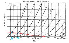
I hand-drew the type 37 since Universal loadline calculator for vacuum tubes - Vacuum Tube Amplifiers - DIY does not support the type 37.
The type 37 is biased at -2.2 V and swings between ~30V and 75V, with quiescent current @ 2.2mA.
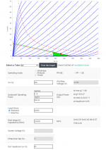
The 6J5 is biased at ~-70V, the plate swings between 240V and 320V, and has quiescent current @ 3.18mA.
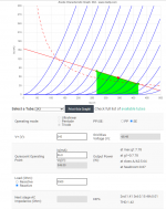
The 2A3 is biased at ~-50V, the plate swings between 270V and 420V, and has quiescent current @ 56.8mA.
I determined the quiescent current by dividing the voltage at the cathode by the cathode resistor.
The "Universal Load Line Calculator" shows that the 6J5/6SN7 operating point is pretty awful. It may actually be worse than the chart shows, since I am unclear on whether or not the "load" that I enter into the "Universal Load Line Calculator" should just be the anode resistor (22 kOhm) or the anode resistor + the cathode resistor (44 kOhm). If I use 44 kOhm, the load line is really atrocious.
6J5 Operating Point?
At this point, I'm not sure what's preventing me from changing the quiescent current of the 6J5 to ~6 from ~3 mA. On the load line calculator, that change moves the 2nd harmonic distortion from 4.39% to 1.22%. This would simply involve modifying the cathode resistor (I believe?). But if I do that, do I compromise the operating point of the 2A3? I'm not against also modifying the 2A3 operating point--I just don't know what happens with the 2A3 if I change the operating point of the 6J5.
Too much gain? Negative feedback?
As I mentioned, the amp sounds great, but I believe I have too much gain. My DAC is ~2V RMS out and the volume control on the amp doesn't need to go much higher than 10 o'clock for things to be pretty loud. I suppose that means I could implement some global negative feedback into the circuit to control that? It would be a fun exercise to implement a switch which would let me turn the feedback element on/off at will to see how it affects the sound.
Otherwise, would moving the overall operating point of the 6J5 "to the left" accomplish a reduction in gain? Or, just by virtue of the tubes used, is the amount of gain present in the circuit set in stone?
Other options?
Obviously one option to pursue is a CCS for the 6J5 and use it to establish a constant operating current of ~6 mA, which should keep it (for the most part) below max dissipation.
For those that want to suggest I scrap it and start over with a single-stage driver--eventually I would like to do that, but for now, I want to move incrementally and see how changes to the circuit affect the overall sound and performance.
Thanks for your time!
Early this year, I completed my first "from scratch" tube amplifier build. I used JE Labs 2A3 Deluxe schematic. Prior to that, I had only built kits (Audio Note Kit DAC 2.1, Bottlehead phono stage, Bottlehead Crack).
The JE Labs amp sounds great (to me!), but as I develop a deeper understanding of the ins and outs of tube amplifier circuit design, I suspect that I could do a lot better. (Those of you who hate two-stage driver circuits and/or 2A3s being driven by 6J5/6SN7, I've read plenty of your posts and am sympathetic to those views.)
I borrowed a rudimentary oscilloscope from a friend and, during my short time with it, observed asymmetrical clipping near maximum output volume using a Type 76 tube. I'm guessing that that had to do with the 6J5 operating point but I am not sure.
Two issues that I want to explore (beyond making sure I have the fundamentals of the operating points down):
- Global negative feedback
- Lowering gain
The circuit can be found here:
JE Labs Arkiv (up to 2008): JE Labs SE300B Classic and Deluxe
But first I want to know if I'm understanding the operating points correctly. I'm attaching a few images illustrating the following:
- Type 37 operating point (input tube)
- 6J5 operating point (driver tube)
- 2A3 operating point
I hand-drew the type 37 since Universal loadline calculator for vacuum tubes - Vacuum Tube Amplifiers - DIY does not support the type 37.
The type 37 is biased at -2.2 V and swings between ~30V and 75V, with quiescent current @ 2.2mA.
The 6J5 is biased at ~-70V, the plate swings between 240V and 320V, and has quiescent current @ 3.18mA.
The 2A3 is biased at ~-50V, the plate swings between 270V and 420V, and has quiescent current @ 56.8mA.
I determined the quiescent current by dividing the voltage at the cathode by the cathode resistor.
The "Universal Load Line Calculator" shows that the 6J5/6SN7 operating point is pretty awful. It may actually be worse than the chart shows, since I am unclear on whether or not the "load" that I enter into the "Universal Load Line Calculator" should just be the anode resistor (22 kOhm) or the anode resistor + the cathode resistor (44 kOhm). If I use 44 kOhm, the load line is really atrocious.
6J5 Operating Point?
At this point, I'm not sure what's preventing me from changing the quiescent current of the 6J5 to ~6 from ~3 mA. On the load line calculator, that change moves the 2nd harmonic distortion from 4.39% to 1.22%. This would simply involve modifying the cathode resistor (I believe?). But if I do that, do I compromise the operating point of the 2A3? I'm not against also modifying the 2A3 operating point--I just don't know what happens with the 2A3 if I change the operating point of the 6J5.
Too much gain? Negative feedback?
As I mentioned, the amp sounds great, but I believe I have too much gain. My DAC is ~2V RMS out and the volume control on the amp doesn't need to go much higher than 10 o'clock for things to be pretty loud. I suppose that means I could implement some global negative feedback into the circuit to control that? It would be a fun exercise to implement a switch which would let me turn the feedback element on/off at will to see how it affects the sound.
Otherwise, would moving the overall operating point of the 6J5 "to the left" accomplish a reduction in gain? Or, just by virtue of the tubes used, is the amount of gain present in the circuit set in stone?
Other options?
Obviously one option to pursue is a CCS for the 6J5 and use it to establish a constant operating current of ~6 mA, which should keep it (for the most part) below max dissipation.
For those that want to suggest I scrap it and start over with a single-stage driver--eventually I would like to do that, but for now, I want to move incrementally and see how changes to the circuit affect the overall sound and performance.
Thanks for your time!
Attachments
Just my two cents.
I don't think that changing the 6J5 operating point would compromise the operating point of the 2A3 (because of the coupling capacitor between the 6J5 and the 2A3). To me the more important issue is the dc-coupling between the 37 and the 6J5. The cathode voltage of the 6J5 has to stay around the 64 V like it is now, unless you would also change the operating point of the 37.
The gain of the 6J5 would drop substantially if you would use a very low value for the anode resistor. But that would make distortion rise (or atleast I think so) so to me this doesn't look like the way to go.
But first I want to know if I'm understanding the operating points correctly
The load for AC is the plate resistor in parallel with the following grid resistor so less than you are using in the calculator or either of the choices you outlined. The operating points are not great but JE tunes by ear so maybe done on purpose. If you don't like the way it sounds you could always try adding a capacitor between the first two stages + grid resistor at the 6J5 and using the B+ you have available at the second stage to get a better operating point.
Thank you for the comments. The remarks on the DC coupling were really eye opening to me and have helped me to better understand the circuit.
The DC coupling means that, though the cathode of the 6J5 is at 64V, the DC coming from the plate of the type 37, at 58V, sets the bias at -8V. Hence both of the comments on DC coupling. So if I use a capacitor, it blocks the DC, and the cathode of the 6J5 would need to be adjusted accordingly (along with the operating point of the 37).
I've got a couple capacitors lying around which would be great for the job.
I actually think that the amplifier sounds good, but I don't have much of a reference for it. Over the next few years I want to experiment with different operating points and tweaks to the circuit and keep learning.
Thanks again for the comments.
I've often read about the possibility of cancelling distortion by setting up stages in a complementary way and that may be how JE's circuit arrived where it sounds as good as it does but i don't know anything about that style of design.
The way I've chosen to approach my own circuits is to try to run each of the amp components in their most linear range. So any suggestions I can think of have to do with setting the op points with linearity in mind.
In this case that would be to increase Vp and Ip of the 37 and lower Vp and raise Ip of the 6J5. Using the same load lines you could get much more linearity of both.
Move the 37 in the direction of Vp=100 , Ip=4mA and the 6J5 toward Vp=230-40V and Ip ± 12mA
You don't compromise the operating point of the capacitor coupled 2a3 with changes to the input and driver tubes so long as you don't increase their current draw so much that they pull down the supply output.
You could (well , I really think should) try changing the operating point of the 2A3 as well , though the output transformer primary impedance has something to say about it. Are you using the Tango? If so, at 2.5 or 3.5K?
Your first post by the way is refreshing . So many times first posts ask big questions without giving any background info, and then anyone feeling helpful has to work to get it out of the OP, often not easily. Yours is a pleasure to read. It also makes me think I'll really enjoy following your posts over time. Prolly learn something from you too. 🙂
Your operating point for the 2A3 is way above anode voltage and dissipation ratings. Are you sure you want to do this? Also, the 6J5 is operated in a very non-linear part of its range. If you're constrained to these operating points, you might want to reconsider the constraints.
All good fortune,
Chris
All good fortune,
Chris
Hello--
After a couple years of tweaking, I thought I'd share my experiences.
Starting from the last post first...
Trying a DC-coupled topology as my first from-scratch build was not wise! I don't know that I ever got it all sufficiently "dialed-in." I had no mechanism by which to ensure that all of the voltages were consistent across channels, let alone where they needed to be to marry nicely with the power stage. On top of that, as Chris pointed out, the operating point was a bad one for the 6J5. A lot of tinkering and measuring later, I've concluded that unless you have a lot of time and patience to acquire properly matched tubes, then test them out in circuit and adjust accordingly, DC coupling is for advanced builders only.
The first thing I did was address my custom-designed power supply. It was a very poorly designed CLCLCRC with lots of resonance. Using PSUDII, I resized some of the capacitors and tried to design in terms of time constants. Also consolidated the two chokes into one, ending up with CLCRC. This shrank the total capacitance of the power supply by a large factor and really tightened up the sound.
Next, I gave Ale Bartola's gyrator boards a spin. This entailed removing the first tube stage altogether and then capacitor-coupling the gyrator-loaded 6J5 to the 2A3. Hugely improved sound. Went from a very "thick" and syrupy sound to something much leaner and more realistic. While I am not always able to get to full output with the 2A3 from my 2V RMS source, it's sufficient most of the time.
After that, I replaced Pete Millet's DC power supply for the 2A3 filaments with Rod Coleman regulators. While I do think they sound better, I don't know that my execution of the Millet boards was all that great, and I wasn't able to do A/B comparison anyway.
The most recent change was replacing my Electro Harmonix 2A3 with JJ 2A3-40 and moving the operating point from 300V @ 60mA to 365V @ 75mA. This also involved replacing the 5U4GB with Schottky diodes. This was among the largest improvements I have made--partly due to increased sonic quality, but also I may finally be providing my Polk Audio Monitor Series 2 from the 90s with the power that they "need." On my bass test tracks (from Lady Blackbird's Black Acid Soul album and Marc Johnson's "Overpass"), deep bass would previously "flub" out before it got to the "bottom." Now there's definition and tone "all the way down," so to speak, and I couldn't be more pleased with it.
I've also gone to LED bias on the input tubes. Experimented on a friend's amp and found that LED-biasing produced the most "solid" and satisfactory sound, especially with regards to bass (compared to resistor-only and capacitor-bypassed resistor).
SS rectification combined with the Coleman regulator's soft-start led me to order one of Broskie's "AC Switches" to avoid a huge B+ spike upon startup. For those who aren't familiar with it (probably everyone?), it lets you switch power to two different AC circuits in sequence. In my case, I first switch on the Antek transformer providing filament power. After the 2A3s are glowing, I can switch on full amp power. Using the 5U4GB, I observed that for ~5-7 seconds after startup, B+ could surge up to 467V before settling to ~385. I'm using 550V max capacitors in the PSU and even though PSUDII predicted ~490V max in the power supply, I knew I would be pushing 550V in this scenario, if not blowing way past it. With the switch, everything is within nominal operating limits upon power up.
For my next tweak, I want to add another set of speaker binding posts. On a recent trip to Japan, I picked up a pair of HC-507U. This has 4-8-16 Ohm taps. It's my understanding that hooking up my speakers will give me something like a 2.5K load instead of the nominal 5K (the Polk speakers are 6 Ohm). That'll give me an additional ~3 watts or so of power, I think.
Anyway. A minor entry in the wider DIY Audio saga. I've made a lot of mistakes, but in the end, everything is sounding better than ever. As others have said, a very rewarding hobby. Looking forward to all my future projects as well as everyone else's here.
- Home
- Amplifiers
- Tubes / Valves
- Verifying Operating Points & Considering Tweaks