I was looking around at different kinds of horns, and decided to brainstorm an idea I had. My idea was instead of using a closed rear chamber, to use a vented one. I was trying to put it in to Hornresp as a 'TH1' but I couldn't get the values just right. So I figured I'd put it here to see what you guys think.
The design is based off the B&C S18H Subwoofer, and originally designed for a 18TBX100
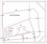
The internal height of the box is 18.5"
The design is based off the B&C S18H Subwoofer, and originally designed for a 18TBX100
The internal height of the box is 18.5"
An externally hosted image should be here but it was not working when we last tested it.
An externally hosted image should be here but it was not working when we last tested it.
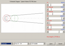
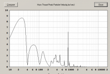
path from rear wave to front wave is verry short(if the center of the speakers is at the 6.6159 point.
if you put the speaker in the mouth it wil work.
you can model the port> ap1=262,1736692 lpt ~50 cm
262 cm2 is imo to narrow for an 18"
if you put the speaker in the mouth it wil work.
you can model the port> ap1=262,1736692 lpt ~50 cm
262 cm2 is imo to narrow for an 18"
Putting the speaker in the mouth would just make it a normal tapped horn though, and only half the air the cone moves goes threw the full length of the horn, I'm trying to get both sides of the cone pushing air threw the horn, and thanks for the port info, that really helps!
Hello abcdmku,
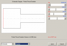
Your diagrams are of a tapped horn with unusual driver placement, and a throat chamber and vent section.
It's just an unusual tapped horn. I'll try to model it here in a minute...
Regards,
Eric
Your diagrams are of a tapped horn with unusual driver placement, and a throat chamber and vent section.
It's just an unusual tapped horn. I'll try to model it here in a minute...
Regards,
Eric
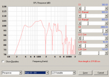
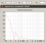
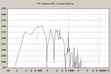
The displacement, particle velocity, and final response chart are all charted at ~300W.
Attachments
Thanks for the help! I'm going to start building this tomorrow, I'll be sure to upload pics of the build! 😀
Hi abcd,
I'm not sure if adding that port would really be considered beneficial... The original design, without that port, actually allows the full use of available Pe, models ~133dB from ~45hz up @1200W and 9mm excursion. Opening up that port, and converting the system to an unusual tapped horn, cuts Xmax limited Pe by 75% and drops average maximum output by about 8dB. The only benefit is slightly lower extension, it's not a worthwhile trade IMO.
Regards,
Eric
That's good to know, I was seeing that on the curves when doing max SPL on Hornresp. But, I don't have 1200 watts of power to put out, only 220 watts RMS 8ohm a channel. When I build this I'm going to have both rear chambers, both the ported and sealed. This is more of just a fun project, to try something different.
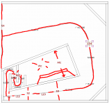
I saw it this way....
woops.... Atc is the wrong orientation- doesn't make a different for the simulation though, I just realized I drew that into the "diagram" wrong.
woops.... Atc is the wrong orientation- doesn't make a different for the simulation though, I just realized I drew that into the "diagram" wrong.
Attachments
Last edited:
Hi mdocod,
By definition the throat chamber attaches through the Ap1/Lpt port to the horn @ S2. If you introduce anything but a very short L12 you are modeling a tapped horn with an offset tap, in other words the port does not attach to S1.
Try setting L12 to .01, and add the old L12 to L23. See if that makes a difference.
Regards,
Hi Oliver,
You're right, I have that "messed up."
I went back and tried those changes- not much difference to the result. (small differences like this don't usually cause monumental changes so that's a blessing)
The more accurate simulation shows me that the result is still going to be a far worse sub than the original design was with the sealed enclosure 🙂
Eric
It's built. and at 40 Hz it is a beast, filled the entire basement with solid bass [with only 50 watts]. Something I noticed with this design, is that when I would walk away from the horn it would not phase in and out. Where my vented enclosure would. I just ordered the iNUKE NU3000DSP when it comes in I will give it one watt and do a spl test when I get the time.
Got any pictures? I'd be interested to see those graphs once you get them. Id be interested to see a front loaded horn with the rear chamber vented, like a lab horn except vented instead of sealed enclosure as opposed to this tapped horn type vented enclosure. Interesting idea, could work out
- Status
- Not open for further replies.
- Home
- Loudspeakers
- Subwoofers
- Vented horn?