Let's talk alignments. Are they necessary in todays computer world? I know many pioneers on the subject created these alignments (tables) and many thanks to their enduring work. But, are they necessary with todays computer calculator design programs (i.e. SE, LspCAD etc.). It seems these tables are not linear and the question is... is it best to use the alignment diagrams (alignment magic) per Qt (with Qb) or is it better to just use the software to find the best curve per application? I have been reading the work done by Thiele, Keele, etc., and it's great but am I constrained to these tables? Keele's work showed sensitivity to parameter variations that make a noticable difference (practice vs. theory) that has me scratching my head. I think Ron E said (it sticks in my head) that the alignments are just points on a continuum and alignments were just a reference for getting from A to B in the old days. Is this true? Should I use accurate software now vs. the alignment tables? Is the software as accurate as the tables.
Thanks,
Mike
Thanks,
Mike
Good software is as accurate as the tables. The tables can be useful for a starting point, but they are just a bunch of useful examples, there's many many more other good ones out there that you can just make up with looking at the modelled responses to suit your needs.
Also taking room influences into account renders the validity of the tables into question for some cases.
Also taking room influences into account renders the validity of the tables into question for some cases.
IMO, designing loudspeakers using simple formulas ("alignments") is a leftover from the past. These formulas typically generate a Butterworth-like solution in an anechoic chamber but completely neglect the effects of the room, the baffle step, voice coil inductance etc.
I would say that they can be starting points for a design, but they should by no means be regarded as final solutions.
In my software Basta! one can apply such formulas to get a starting point. From there one will usually tweak the parameters of the design to acheive whatever design goals there are.
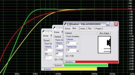
Below is a simulation using three common "alignments" with the room gain of an average room, the baffle step of a 20 cm wide baffle and also considering the voice coil inductance.
Interestingly, the same holds for crossover filters; table filters are rarely optimal when the response of the entire system is considered. Using a simulator that simulates everything, or even better using measured data and a simulation of the electrical parts gives a much better opportunity to end up where you want.
For example, the wide hump around 500-1000 Hz in the example above could be brought down by tweaking the values of the filter components, or adding some more components.
... so my bottom line is that today's simulators are much better at helping you reach a reasonable design than the simple alignment formulas from the past are.
I would say that they can be starting points for a design, but they should by no means be regarded as final solutions.
In my software Basta! one can apply such formulas to get a starting point. From there one will usually tweak the parameters of the design to acheive whatever design goals there are.
Below is a simulation using three common "alignments" with the room gain of an average room, the baffle step of a 20 cm wide baffle and also considering the voice coil inductance.
An externally hosted image should be here but it was not working when we last tested it.
Interestingly, the same holds for crossover filters; table filters are rarely optimal when the response of the entire system is considered. Using a simulator that simulates everything, or even better using measured data and a simulation of the electrical parts gives a much better opportunity to end up where you want.
For example, the wide hump around 500-1000 Hz in the example above could be brought down by tweaking the values of the filter components, or adding some more components.
... so my bottom line is that today's simulators are much better at helping you reach a reasonable design than the simple alignment formulas from the past are.
Points on a continuum is one way of looking at alignments. I am not a proponent of designing to alignments, but I do think they can serve a reasonable starting points to design. In the simplest case, an alignment is just a chosen box size and tuning frequency. Some of these choices work better than others. Alignments represent an ordered, mathematical way of looking at the relationship of Vas/Vb and Fb/Fs to frequency response.
The strength of a chain is defined by its weakest link, and the weakest link in the T/S theory is the simplifying assumptions behind it. In most T/S models, linear halfspace behavior is assumed, this means a box behind an infinite baffle, and no room or furniture in front of it. Obviously being on a finite baffle in a room changes things somewhat, as Svante's sim shows admirably.
Trying to account for uncontrolled variables (room size, construction, furnishings, driver nonlinearity, etc..) is not a simple thing to do. How would you make a program that a layman could use that would allow entry of the complex situation at hand? You have to stop somewhere and T/S theory helps design to the simpler driver variables quite well. Once you include damping terms and other variables like voice coil inductance you can't even represent the system with the traditional alignments anyway.
Parameter variations are important to understand, the most important of which is compliance variation over the life of the speaker. The compliance will increase and Fs will decrease in turn because the mass of the speaker won't change unless you are in a REALLY dusty environment 😉 Luckily, response changes due to compliance variation are pretty minor. As long as you measure your speaker before designing a box for it, you shouldn't have to retune due to aging.
For Svante, I am curious what defines the Ohman curve. Is it another curve fit like the others? BTW, I wouldn't call the Keele/Small/Margolis design methods alignments, although they are two ways of curve fitting the maximally flat QB3 and Equiripple C4 alignments to get a simplified approach.
Ron E said:Parameter variations are important to understand, the most important of which is compliance variation over the life of the speaker. The compliance will increase and Fs will decrease in turn because the mass of the speaker won't change unless you are in a REALLY dusty environment 😉 Luckily, response changes due to compliance variation are pretty minor. As long as you measure your speaker before designing a box for it, you shouldn't have to retune due to aging.
Indeed understanding is important, and that is where simplifications can have its place. A while ago, when I implemented those alignments I tried to derive my own version of the "design suggestions" as I call them in Basta!. It was based on the fact that changes in compliance make very small changes on the response. The math gave me a formula which was rather similar to the three more well known equations, so I actually left it out. But the journey through the derivation of the equation was certainly worthwile anyway. This is why I encourage people to try to dig beyond the formulas and try to understand when they are valid and how they are derived. They are good starting points, but almost all formulas/models have some sort of limitations.
Ron E said:For Svante, I am curious what defines the Ohman curve. Is it another curve fit like the others? BTW, I wouldn't call the Keele/Small/Margolis design methods alignments, although they are two ways of curve fitting the maximally flat QB3 and Equiripple C4 alignments to get a simplified approach.
Ah, yes, maybe I am wrong in calling them "alignments". They will result in near butterworth alingments if Qts is near 0.38.
For the Öhman equations, they are visible on the "design suggestions" tab in Basta!. The .../(1+Viso) is added by me to account for the virtual box volume increase due to isothermalisation from the stuffing.
An externally hosted image should be here but it was not working when we last tested it.
FYI: Ingvar Öhman is sort of a Hifi Guru in Sweden who has devoted most of his life to loudspeaker design. He made up those formulas some 10-20 years ago, I think, but he actually isn't very fond of them himself (he calls them "toy formulas"). Stereophile recently made a review of one of his designs:
http://blog.stereophile.com/he2007/051607sjofn/
Group delay is frequently neglected in speaker design. Here is another "toy" that is able to display group delay:
http://tube.fw.hu/Speaker_impedance.xls
Room interaction is not accounted for in my model, though.
http://tube.fw.hu/Speaker_impedance.xls
Room interaction is not accounted for in my model, though.
Svante said:
The .../(1+Viso) is added by me to account for the virtual box volume increase due to isothermalisation from the stuffing.
Sorry, it should be .../(1+0.4*Viso), obviously.
Hi,
the alignments of yesteryear are based on an arbitrary performance
criteria, e.g. maximally flat for butterworth, equiripple for Chebyshev
etc, but as described above they do suit real room acoustics.
So you change your abitrary criteria. B&W for example use near 4th
order Bessel alignments which match well with rooms, and can be
combined with an active high pass 1<Q<2 filter depending on the
room to give a more extended 6th order alignment.
As stated above classic say 4th order and 2nd order L/R alignments
are alive and well as acoustic alignments but the practise of
using acoustic alignments has not transferred to the bass end.
Presumably due to the unknowns, room size, shape and speaker position.
My favourite vented alignments have an accelerating slope the
lower you go and you try to suppress an obvious "kneepoint".
No doubt the mathematically inclined could find the "criteria" that
would cause this and define the "family" of filters it is part of.
Detuning a standard Butterworth by 0.7 seems to work well :
🙂/sreten.
Attachments
Yes, room compensation is tricky. As a DIYer one could in principle optimise the speakers for a particular placement in a particular room. Then again one will probably want to use the speaker in some other room later on. Commercial speakers must optimise towards an average room.
Typical rooms are resonant in the bass region, but resonances can hardly be compensated for unless the exact room and placement is known. OTOH all reasonably sized rooms exhibit some sort of bass lift, and this can be taken into account. It will not remove resonances, but to some extent compensate the overall bass lift that occurs in all rooms.
The bass lift I showed in my simulation above is almost a straight line from 100 Hz to 20 Hz, lifting 20 Hz by ~10 dB. It is not a simulation of an actual room, but a lift that is reasonable to compensate against.
Given this compensation, new equations could be derived, but they will not be scalable (frequency-wise) as the old ones were. The room compensation should not move if the driver fs does. So, while this is possible, I think time has run away from the "design equations" since almost everyone can afford a computer and simulation software today.
Svante said:
The bass lift I showed in my simulation above is almost a straight line from 100 Hz to 20 Hz, lifting 20 Hz by ~10 dB. It is not a simulation of an actual room, but a lift that is reasonable to compensate against.
Hmmm.......
The smoothest bass lift you are going to get is with the speakers
1/3 along each room diagonal - not a typical placement. so failing
that the bass unit needs to be distanced away from the room
boundaries by dissimilar distances, the most important criteria
to me is the length of the shortest distance.
Who Stole The Bass? / No One Stole The Bass
Anthony H. Cordesman & Martin Colloms, April, 1987
http://www.stereophile.com/features/44/index.html
Is where that model comes from - and it does not apply to
placement near boundaries or speakers with bass drivers
near the floor, see page 4 of the article for the context.
The whole article is quite entertaining ..... relatively .....
🙂/sreten.
Hi,
Interestingly if you ignore the 5dB/octave given on the graph in
said article as it appears to be nearer 3dB per octave and use :
+1dB at 100hz, +4dB at 50Hz and +7dB at 25 Hz and apply
them to the red line shown in the graphs above you get :
100Hz flat , 50Hz +1dB and 25hz - 2dB, which is not too shabby.
I suspect the 5dB/octave is a conceit to make sealed boxes
look better in the modelling, but is should be obvious from
the principles you could bunch up the boundary distances
for sealed boxes to get the optimum room gain shape.
🙂/sreten.
Svante said:FYI: Ingvar Öhman is sort of a Hifi Guru in Sweden who has devoted most of his life to loudspeaker design. He made up those formulas some 10-20 years ago, I think, but he actually isn't very fond of them himself (he calls them "toy formulas"). Stereophile recently made a review of one of his designs:
Hi Svante,
Just wondering have you met or worked with Ingvar?
Pete B.
As others have noted, an "alignment" is just a point along a continuum. A given alignment, or tuning, may or may not result in the expected sonic characteristics - room acoustics also plays a major role.
The difference in room acoustics from one room to another, and from one location to another within a given room, is usually comparable to (if not greater than) the difference between one vented box tuning and another.
It's not easy to accurately model the room acoustics at the same time you're modelling the loudspeaker enclosure. For one thing, at the design stage you may not yet know exactly where the speakers will end up.
My suggestion (and it's hardly original) is to make provision for changing the box tuning so that it can be adapted to its environment. I use Precision Ports' modular system, and join the sections together by wrapping the junctions with electrical tape instead of gluing them. Different length center sections (or no center section at all, or no inner flare) can be used to get different tuning frequencies.
http://www.psp-inc.com/; available from Madisound and Parts Express.
Duke
Hi Svante,
Just wondering have you met or worked with Ingvar?
Pete B.
I can answer that for Svante.
Yes we have met, but we have not worked togather, other than that we (and some other people) a few times have tested amplifiers for the Swedish HiFi magazine Music & Audio Technology (Musik & Ljudteknik).
Svante is a really great guy, and I recommend his simulation programs for anyone in use of such programs (personally, I prefer using my pencil and some squared paper though*).
He is a teacher at the royal institute of technology i Stockholm by the way, and a very respected one. Just a few weeks ago he was awarded as he best teacher on the institution.
Finally, having said that - I'd like to correct him! 😉
The toy formulas of mine that he is referring to (yes that is what I call them, since such formulas at best can be used to play with, unless you are doing PA-systems for out door use) does not have their origin 10-20 years ago, but rather some 33 gears ago, or so. 😎
Vh, iö
- - - - -
*Because it is faster, and because predicting the physical behavior of the box is never the problem anyway. The difficulty is always to determine what you want the box to do, not making it do it. 🙂
But as said - if you need a simulation program, Svantes is probably the best.
PB2 said:
Hi Svante,
Just wondering have you met or worked with Ingvar?
Pete B.
Ah, I missed that question, and I think Ingvar answered it well.
The short answers are yes we have met, and "a little". We have done some testing together on a non-profit basis. Also, Ingvar helped me with the default room gain curve in Basta! and of course the "Öhman" equations under "design suggestions" are his.
IngOehman said:
I can answer that for Svante.
Yes we have met, but we have not worked togather, other than that we (and some other people) a few times have tested amplifiers for the Swedish HiFi magazine Music & Audio Technology (Musik & Ljudteknik).
Svante is a really great guy, and I recommend his simulation programs for anyone in use of such programs (personally, I prefer using my pencil and some squared paper though*).
He is a teacher at the royal institute of technology i Stockholm by the way, and a very respected one. Just a few weeks ago he was awarded as he best teacher on the institution.
Finally, having said that - I'd like to correct him! 😉
The toy formulas of mine that he is referring to (yes that is what I call them, since such formulas at best can be used to play with, unless you are doing PA-systems for out door use) does not have their origin 10-20 years ago, but rather some 33 gears ago, or so. 😎
Vh, iö
- - - - -
*Because it is faster, and because predicting the physical behavior of the box is never the problem anyway. The difficulty is always to determine what you want the box to do, not making it do it. 🙂
But as said - if you need a simulation program, Svantes is probably the best.
Just noticed your post and Svante's. I didn't know that you were on this board Ingvar, when I posted this to Svante. Then I saw your discussion of the QM10 in the other thread.
I had the QM10's in my home for about a month, as I think you know, very nice, impressive!
Pete B.
Here is a link to an article I wrote on this subject
http://sound.westhost.com/articles/cscaling.htm
Several people have talked about turning this into a program but so far no one has, (I don't like programing so I am not going to).
This article deals specifically with qb5 alignments, but other can be scaled in the same way as long as the double or half qt rule is followed.
rcw.
Any subject which has a heavy dose of math will elicit very interesting responses...
Just a couple of points to illustrate my POV:
1. It's all about tradeoffs. Alignments are a way to help you decide what is most important for you and what you sacrifice by choosing what is most important. Example: is transient response the most important for you? Go for a Bessel alignment and be prepared to lose out (all other things remaining equal) on flatness of passband and sharpness of rolloff.
2. Alignments are an approximation - like all other models in this world. If you want to calculate the force required to move a speaker halfway across a room at 1mph, you would use Newton's laws and not Einstein's. Similarly if you want to build a system to listen to in your living room at 5 watts RMS (pretty loud, by the way), T/S parameters and old-fashioned alignments are great and sufficient!
3. Are alignments points on a continuum? Yes and no. For sealed enclosures yes. For vented, in principle yes, but if a vented enclosure falls even slightly off its intended alignment (QB3, SC4 or whatever you have) it will sound terrible - which is why historically vented enclosures started out with a bad name. So from a practical point of view it is better to treat vented enclosure alignments as NOT being on a continuum.
My 2 cents'
-Ram
I just want to agree on what was said about vented alignments. They are more delicate, and a lot of them out there sounds really terrible.
On the other side - with vented alignments there are possibilities to shape the response in much more detail, to fit the rooms frequency depending loading, and I believe that well done - it is the way to go for most full range speaker designs. This "shapability" a fantastic resource, if you know what you are aiming at. I believe that's where you find the real difficulty - to know which isolated properties you want from the loudspeaker it self (as seen in an anechoic room or in a simulation program), to make it perform accurately together with the room, together with the other loudspeaker/the stereo system, and together with the listener.
With a closed box the only variables are resonance frequency and Q. That might be enough for the application in mind. Then again - sometimes it isn't.
Best regards, Ingvar
I agree Ingvar, and I also believe that people often put too much emphasis on the amplitude response and flatness, when they would be much better off tuning for large signal performance and a shaped response as you point out. The real bad vented alignments are often tuned too high and have quite poor large signal performance below their tuning frequency.
I find tuning low, with a softer rolloff usually enhances large signal performance, and is a better match for room gain. I also do not believe that vented designs are overly sensitive to driver parameters within reason. There have been AES articles on jaming a driver into a desired "alighnment".
I think of the classical alignements is a sense as reference points that are easy to remember. I wrote this about vented systems:
http://www.diyaudio.com/forums/showthread.php?postid=1260665#post1260665
Pete B.
- Status
- Not open for further replies.
- Home
- Loudspeakers
- Multi-Way
- Vented alignments