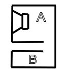
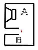
What would be the best way to go about putting together a sim for something like the attached image? It's a slot-loaded vented alignment of volume A with an additional "resonance chamber" of volume B located below the slot vent. Or would this arrangement just act like a larger vented alignment of volume = A+B?
Attachments
If only there's enough space between the rear panel and the vent, I believe we should see the volume as a whole.
I think can kind of see what your trying to do, that the second cavity would resonate and shape the frequency response, yes?
however, because it's a sub, I'll assume you want a band width of say 20hz to 100hz, for example. after all, a sub woofer is designed to produce sub sonic frequencies.
at the highest wavelength; 100hz, the length of the wavelength is around 11.3feet long. so it takes that length to finish one cycle. chances are, your box isn't going to be that long.
if the box was, for simplicity of explanation a tube 5.6 feet (half of a 100hz wavelength) long with the speaker on one end playing a 100hz tone and the other end of the tube is a sealed wall.
then the sound pressure at the flat wall at the back would be out of phase with the back of the speaker. ( draw a sine wave starting at maximum amplitude, going down past 0v then to minimum amplitude, then back to 0v and then maximum amplitude. the speaker box is not long enough for that entire wavelength to be formed, it is only half a wavelength long so by the time the wavelength reaches the back wall, it is only at half of the wave length cycle. like if you cut your sine wave drawing in half and threw the second half away)
if the box was only 2.3 foot deep, it would only be 90 degrees out of phase. meaning the pressure difference from front to back would not be too different.
in your design, the sound wave would be traveling from the speaker, to the cavity "B" and back to the speaker and that distance is unlikely to be long enough.
my point is, that at deep bass frequencies, the entire cavity roughly pressurizes evenly in smaller boxes. the box would have to be VERY long to pressurize in an uneven way.
also, a smaller cavity "B" inside a larger cavity "A" would resonate at a higher frequency then the larger cavity "A". so for sub bass applications, it may not be as useful as it appears.
anyway, this is at the very high bass frequencies, (100hz) and if we go down to 20hz, then the wavelength will be just over 57 foot!
dam..
did I do it again?
did I..
did i start rambling again?
sorry guys..
If only there's enough space between the rear panel and the vent, I believe we should see the volume as a whole.
Agreed, with the caveat that in cab's pass-band there's no lengths long enough to create any Eigenmodes, such as occurs in a [ML]TL. At this point, a notch is created that shifts down in frequency as the vent moves towards the driver.
GM
Yeah, i'm with CLS & GM on this. So you might as well avoid any uncertanties, & place the slot @ the bottom for eg.
Yes.Or would this arrangement just act like a larger vented alignment of volume = A+B?
Hi Brian,
Looks like the devil is still in the details, depending on the exact dimensions you might be looking at something like the Atlantic HPAS technology, or something as in the Clements patent US 2011/0058700 A1. Also, check all the prior art.
So, yes, if done correctly this would work. Or, if done incorrectly it'll just be a bigger overall volume w/ a single port.
It might be possible to do this in Hornresp, but maybe it'll take AkAbak. If I find the time I'll take a look at it.
Regards,
Attachments

Last edited:
An externally hosted image should be here but it was not working when we last tested it.
I know absolutely nothing about this cab and I don't read or speak japanese.
However the Lockwood Major (using 15" TannoyDC) was rather similar ie main volume vented into a ported chamber. There was some added acoustic resistance between the two parts as the opening was covered in hessian and may be some fibreglass. I only saw a photo of the insides and it was not clearly visible.
FWIW Lockwood Majors had a reputation for excellent sound with plenty of low bass.
On the down side they were also known to kill woofers due to excessive excursion if driven with a bit of enthusiasm.
PS: Embedded linky no worky (at least not for me) so here's the regular version:http://rasenkan.blog.so-net.ne.jp/2008-11-26-1
Looks like the devil is still in the details, depending on the exact dimensions you might be looking at something like the Atlantic HPAS technology, or something as in the Clements patent US 2011/0058700 A1. Also, check all the prior art.
Hmm, like the [ML]TL situation, this is a band stop filter: http://users.cms.caltech.edu/~ps/All.pdf
GM
Hi Brian,
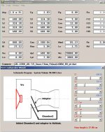
Here is a multipurpose AkAbak script. I took a vented enclosure OD simulation of something I think looks like the JBL jet port, and attached a second chamber (Chamber2) @ the output of the first chamber (Vrc). By changing one node assignment in the script you can change the tap point. I tried to document this in the script too. Obviously, you can modify the horn sections as you see fit.
The attached file is the Akabak script, to be able to attach it here I changed the file extension from .aks to .txt. You'll have to change it back to .aks to be able to use it.
Regards,
Attachments
Last edited:
Looks like the devil is still in the details, depending on the exact dimensions you might be looking at something like the Atlantic HPAS technology, or something as in the Clements patent US 2011/0058700 A1.
Yep, that is actually where I'm getting my "inspiration" from, though it is a design I've considered earlier (might have even mentioned it here), just never knew how to sim it. Basically the idea is to use the extra resonance to deal with the out of band "organ-pipe" effects caused by the vent. This could be of benefit for any alignments that use a vent, particularly bandpass alignments, if the increased box size requirement is not a major issue.
My next concern is if the placement of the entrance to the resonance chamber is optimal, i.e. should it be at the end of the vent, or somewhere along the middle to get the best results?
Most of the images I've seen of something similar seem to have the vent for the resonance chamber of the same or similar cross-sectional area as the main vent, and there may be some logic behind this as well that I'm not aware of.
Hmm, like the [ML]TL situation, this is a band stop filter: http://users.cms.caltech.edu/~ps/All.pdf
Yep, that's exactly what I think it is. If implemented correctly, of course 🙂
The attached file is the Akabak script, to be able to attach it here I changed the file extension from .aks to .txt. You'll have to change it back to .aks to be able to use it.
Thanks. I gave the script a try. It seems to mostly work as expected (modifying the area of the "tap" vent moves the resonance point up and down the impedance curve). However it seems to fall apart at lower frequencies, i.e. Akabak predicts a much greater change in response than I'd expect. For example, set the "tap" vent's surface area to 1 x 10 e-4 - Akabak says that would result in a huge notch in the response at 30 Hz, something that seems a bit unrealistic.
...Akabak says that would result in a huge notch in the response at 30 Hz, something that seems a bit unrealistic.
I'm not testing or reading on the subject but it should be right; Tuned Acoustic Absorber/Helmholtz Resonators.
Tuned Acoustic Absorber - DEICON
Attachments
@ GM
Thanx for the PDF link, good stuff 🙂
@ Brian Steele et al
At what point does B due to the shelf/port depth, become a "normal" part of A's area, or not & therefore considered as something other than a "standard" reflex box ?
If the shelf was for eg half the box depth, as in my screenie, A & B would surely be as one !
Attachments
The vent has an end correction and once the gap to the back wall becomes < this gap, then they theoretically become separate chambers, but even then it seems like they would be summing to drive the vent, so my SWAG is that as drawn, 'B' will not become a band stop filter.
GM
GM
- Status
- Not open for further replies.
- Home
- Loudspeakers
- Subwoofers
- Vented alignment with separate resonance chamber