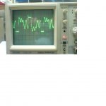
yes, this is what happens. Vds is only well defined when a switch is on. once both switches are off, the stored energy in various inductances and capacitances is allowed to ring.
A different snubber might reduce the ringing if it is causeing EMI issues.
A different snubber might reduce the ringing if it is causeing EMI issues.
Looks like very high leakage inductance. You can tell by the clamped waveshape right after when the switches turn off. That's the diode conducting in the other FET. Timebase is long so energy is probably high. Capacitance looks high also.
Try winding a better transformer.
Try winding a better transformer.
Vds osc.
Thanks for replying.
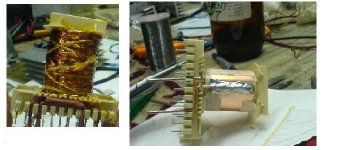
Regarding the power transformer I used copper foil for the primary since the high value of the current. I can not use enamelled copper for 20-25 Amps in the primary. I first wound two copper foils connected as parallel for the 1st primary then the enamelled copper for the secondaries then finally 2nd primary same as the first one. I beleive this is a good way to increase the coupling between primary and secondary. Please check the attached pic.
Thanks for replying.
Regarding the power transformer I used copper foil for the primary since the high value of the current. I can not use enamelled copper for 20-25 Amps in the primary. I first wound two copper foils connected as parallel for the 1st primary then the enamelled copper for the secondaries then finally 2nd primary same as the first one. I beleive this is a good way to increase the coupling between primary and secondary. Please check the attached pic.
Attachments
Re: Vds osc.
How many turns on primary/secondary and how did you wind the secondary? Is it one layer? Can you measure leakage inductance? And just curious what is the switching frequency?
How many turns on primary/secondary and how did you wind the secondary? Is it one layer? Can you measure leakage inductance? And just curious what is the switching frequency?
Hello,
1 st. ---Primary is (4) layers of copper foil. (2 foils are soldered together to handle the high current)
2 nd.---My aim was to wound the secondaries as one layer. But the secondaries ((9+9) turns) did not fit on the coil former. Since (7+7) turns covered the available winding area the remaining (2+2) were wound on them.
3 rd.---Again the remaining primary same as the 1st one were wound as (4) layers.
I do not know how to measure the L(leakage). If you know a way how to do it please tell me. I have a L(meter).
Vin=12 Volt
fs= 46 kHz
Bmax=0.12 T
ETD 59
Thank You.
Hi,
I also had this problem, but I didn't whan't to rewind the trafo (though I eventualy will), so I just put a resistor acros both primaries.
nejc
I also had this problem, but I didn't whan't to rewind the trafo (though I eventualy will), so I just put a resistor acros both primaries.
nejc
To measure leakage inductance short secondaries and measure primary inductance. In the push pull you want take measurements as 'seen' from the switch during the one cycle. So you want to short the secondary from say 'dot' to ct and measure primary 'dot' to ct.
Most likely the measurements will be low and difficult to measure so measure the secondary by shorting the primary. The leakage inductance reflected to the primary would be the (np/ns)^2 times less.
What are the values of your snubbers that you have on the primary/secondary?
Most likely the measurements will be low and difficult to measure so measure the secondary by shorting the primary. The leakage inductance reflected to the primary would be the (np/ns)^2 times less.
What are the values of your snubbers that you have on the primary/secondary?
Hello,
When the secondary is shorted, the measured primary (L) = 3.6 uH.
When the secondary is open, the measured primary (L) = 14.4 uH.
Snubber ; R=100 ohms, C= 100 nF
Best Regards
When the secondary is shorted, the measured primary (L) = 3.6 uH.
When the secondary is open, the measured primary (L) = 14.4 uH.
Snubber ; R=100 ohms, C= 100 nF
Best Regards
What do you mean 9+9? 18 turns with secondary center tapped 9-ct-9? If so, did you take the center tap at the center of the layer?
Do you feel like winding another transformer? Try winding 1 secondary in first layer assuming that the 9 turns is one winding, then all of the foil, then the 2nd secondary. Tie the center tap on the secondary externally.
This should reduce the leakage inductance greatly and to help even more double up on the wires since the 9 turns will not fill up window width now. Go up 1 gauge if it does not fit.
Please post results it you wind it.
- Status
- Not open for further replies.
- Home
- Amplifiers
- Power Supplies
- Vds oscillation