[wiki=Main Page]return to diyAudio Wiki Main Page[/wiki]
[wiki=Behavioral Modeling]back up[/wiki]
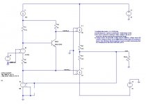
This example shows basic modeling of the effects of temperature using a Vbe multiplier, such as for controlling output stage bias, and also a DC servo.
I1 stands in for the VAS, generating 10mA. A Vbe multiplier (R1, R2, R3, and Qbias) maintains a voltage spread between Vspread_h and Vspread_l. The output stage is G1 and G2, voltage controlled current sources. The output is fed back to E1, a voltage controlled voltage source, which acts as a servo to keep Vout at 0V. V3 creates a voltage that tracks temperature, it controls E2 which is another VCVS which can be used to null out the change in Vbe for Qbias.
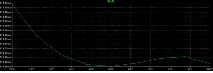
The simulation is the .op command, which finds the DC operating point of the circuit. The temperature is stepped from 20C to 100C in 10C increments. The plot shows emitter resistor current vs. temperature. The gain of E2 has been set to counteract the temperature induced change in Vbe for Qbias, thereby keeping the emitter resistor current nearly constant over temperature.
Correlation of this approach to the real world is unknown and depends on how accurately the temperature effects are modeled in the device model. Your mileage may vary. The reason for putting this example here is to provide another example of behavioral modeling that will ideally stimulate the reader who is unfamiliar with such techniques to start thinking/reading/studying about it.
For a very different approach on using spice for temperature simulations, see Ch. 13 in the Audio Power Amplifier Design Handbook by Doug Self.
Credit: This experiment was inspired by an example posted by Bob Cordell elsewhere on diyAudio.
[wiki=Behavioral Modeling]back up[/wiki]
This example shows basic modeling of the effects of temperature using a Vbe multiplier, such as for controlling output stage bias, and also a DC servo.
I1 stands in for the VAS, generating 10mA. A Vbe multiplier (R1, R2, R3, and Qbias) maintains a voltage spread between Vspread_h and Vspread_l. The output stage is G1 and G2, voltage controlled current sources. The output is fed back to E1, a voltage controlled voltage source, which acts as a servo to keep Vout at 0V. V3 creates a voltage that tracks temperature, it controls E2 which is another VCVS which can be used to null out the change in Vbe for Qbias.
The simulation is the .op command, which finds the DC operating point of the circuit. The temperature is stepped from 20C to 100C in 10C increments. The plot shows emitter resistor current vs. temperature. The gain of E2 has been set to counteract the temperature induced change in Vbe for Qbias, thereby keeping the emitter resistor current nearly constant over temperature.
Correlation of this approach to the real world is unknown and depends on how accurately the temperature effects are modeled in the device model. Your mileage may vary. The reason for putting this example here is to provide another example of behavioral modeling that will ideally stimulate the reader who is unfamiliar with such techniques to start thinking/reading/studying about it.
For a very different approach on using spice for temperature simulations, see Ch. 13 in the Audio Power Amplifier Design Handbook by Doug Self.
Credit: This experiment was inspired by an example posted by Bob Cordell elsewhere on diyAudio.
Attachments
Last edited: