Hello All,
Yesterday I came across SONY TA-N1 schematic and one thing captured my attention.
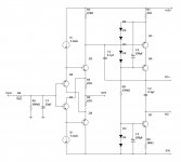
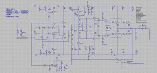
See its simplified front-end topology attached.
Diamond IPS drives a Hawksford-cascoded VAS at its top end, loaded with CCS at the bottom.
SONY engineers refused from symmetric push-pull VAS, used by many others in this kind of situation, in favor of SE+CCS configuration.
Advantages I see:
- rock solid VAS quiescent current;
- probably slightly different harmonics profile (better one?).
Potential disadvantages:
- slightly asymmetric slew rate;
- slightly asymmetric clipping behavior.
What do you think? What would be your preference and why?
Cheers,
Valery
Yesterday I came across SONY TA-N1 schematic and one thing captured my attention.
See its simplified front-end topology attached.
Diamond IPS drives a Hawksford-cascoded VAS at its top end, loaded with CCS at the bottom.
SONY engineers refused from symmetric push-pull VAS, used by many others in this kind of situation, in favor of SE+CCS configuration.
Advantages I see:
- rock solid VAS quiescent current;
- probably slightly different harmonics profile (better one?).
Potential disadvantages:
- slightly asymmetric slew rate;
- slightly asymmetric clipping behavior.
What do you think? What would be your preference and why?
Cheers,
Valery
Attachments
Just ran a simulation
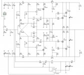
What I just did - I took my simple CF-FET 2.0 based amp model (its symmetric front-end is built and tested many times) and removed the whole bottom half of it, exchanging it with 2 CCSs.
Simulated performance is virtually unchanged. Same level of distortion (rather low), same open loop response and stability margins. As expected - slew rate became very slightly asymmetric - it goes up a bit faster than down, just because the current pulling down is constant, but the one pulling up can be higher than that.
I'm going to test it live - I've got the symmetric option already on my test bench, just need to modify the 2-nd channel to have it arranged in SE+CCS way.
Hope live measurements + listening are going to show something interesting...
Attachments
Valery
If I can put a my 2 cents. I have made recently a IPS board based on the N1 or ER1 sony series (must finish it up someday).
The schematic in first post --> I have added +/-15V votage there, collector of the Q4 transistor can be referenced directly to -15V and Q3 can be cascoded so the power loss will be nicely splitted in between transistors, further if all 4 input transistors will be biassed very close, than there will be a very little problems with offset (just a screwdriver servo should do the job).
Last year I have made nearly 10 differend IPS board designs, some of them were fully symetric and some not.
The best feedback I am getting from the CCS based VAS designs.
Some of the push-pull VAS IPS boards have excellent measurements but the sound is kind of dry, clinic, with no colours (have no idea how to describe it properly).
So my vote is for not symetric, not necessary low THD designs (like post no.2 on the right). I have made small 6 transistor amp which sound better than other 20-30 tranistors amp I have build.
Simple stuff can be really good too.
Regards Peter
Attachments
@vzaichenko, Apex published a couple of similar Sony inspired amplifiers in his "100W Ultimate Fidelity Amplifier" topic. Apex A15 in post #5972 http://www.diyaudio.com/forums/soli...imate-fidelity-amplifier-598.html#post4572332 and Apex FX9 in post #6297 http://www.diyaudio.com/forums/soli...imate-fidelity-amplifier-630.html#post4617258 There are also a couple of simulations of the Apex A15 in the posts following the linked ones.
Terry built the FX9 and you can see his working prototype in post #6337 http://www.diyaudio.com/forums/soli...imate-fidelity-amplifier-634.html#post4620983 Also, if I remember correctly, he mentioned that the DC servo had to work real hard on his amplifier.
Terry built the FX9 and you can see his working prototype in post #6337 http://www.diyaudio.com/forums/soli...imate-fidelity-amplifier-634.html#post4620983 Also, if I remember correctly, he mentioned that the DC servo had to work real hard on his amplifier.
@Borys, could you specify/explain the types of dual T1 and T2 transistors, please?
Best regards,
Kuba
Best regards,
Kuba
@Borys, could you specify/explain the types of dual T1 and T2 transistors, please?
Best regards,
Kuba
Hi Kuba,
BC846CPD can be used very successfully there.
See the datasheet here:
ON Semiconductor BC846-848CPD
Cheers,
Valery
Those dual BC transistors are really good, nice for CFP LTP front end too 😀
There is a lot of nice smd parts availible, so if we marry a few minimelf resistors with couple of fancy smd transitors the resault can be very promissing.
Valery
I just spotted there is no gate clamp diodes networks at latfets (this is prapobly only a sim schematic), I am not using them too, I had some fail of the drivers and those internal zeners/diodes network are doing the job just fine.
The schematic on the right looks really cool!!
There will be a lot of voltage wasted from the rails, maybe a bootstraped OPS will do the job ? Take a look at the sony ta-a1es cool idea too.
Regards
Last edited:
Those dual BC transistors are really good, nice for CFP LTP front end too 😀
There is a lot of nice smd parts availible, so if we marry a few minimelf resistors with couple of fancy smd transitors the resault can be very promissing.
Valery
I just spotted there is no gate clamp diodes networks at latfets (this is prapobly only a sim schematic), I am not using them too, I had some fail of the drivers and those internal zeners/diodes network are doing the job just fine.
The schematic on the right looks really cool!!
There will be a lot of voltage wasted from the rails, maybe a bootstraped OPS will do the job ? Take a look at the sony ta-a1es cool idea too.
Regards
Hi Peter,
You-re right, particularly these Hitachi/Renesas devices have got internal zeners/diodes, working just fine.
Yes, some voltage is wasted, but I normally don't care, just increasing the rails accordingly 😉
TA-A1ES is interesting - same front-end topology (as TA-N1) and controlled rails for the output stage 😎 Very elegant engineering.
I'm very happy with my NS-OPS at the moment as well as my current-driven VAS front-ends, however, I'd like to try a combination of a diamond IPS and a single-end current-driven VAS. Looks rather promising to me 😉
I experimented with symmetric designs a lot and some of them are showing excellent performance, but I'm coming to a conclusion that SE-driven CCS-ed VAS topology makes a lot of sense.
Thank you for your comments!
Hi Guys
Regarding gate protection: To me it makes the most sense to add a few 20-cent diodes to the board rather than lose a 5-dollar part. I saw a lot of mosfets destroyed in the 80s because the engineer didn't use discrete diode protection.
Symmetricc vs asymmetric: I prefer symmetric circuits and they usually take less board space. It is easy these days to get similar very-low-THD from either and slew rate asymmetry is not actually problematic provided it exceeds the signal requirement.
There is a potential for pole-doublets with the symmetric circuit because the gains of the circuit halves might be similar rather than identical. One would suppose that identical gain could cause a doubled rolloff rate? In any case, it is best to get the circuit halves close in gain even if individual complementary stages are not matched.
Persoanlly I believe the sound of asymmetric circuits like the Thompson, lin whatever it is called, is flawed. The opamps based on this topology sound the same since they are the same circuit. Symmetric circuits optimised for low THD sound neutral and if you asre not used to truly accurate sound, this will strike you as "lifeless", at least initially. I am always pleased when I cannot hear the equipment!
Note that in the asymmetric circuit, slew can be balanced by adding a small cap (15p) from the CCS collector back to the base of the current-clamp BJT, which should have a small series base-stop. Valery's circuit for the CCS would need the regulator IC replaced by a BJT for this to work.
Valery, always interesting threads from you!
Have fun
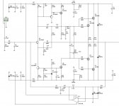
I made this simulation, inspire by APEX. Single ended VAS, make H2 dominant.
Local FB from the pre-driver is forcing your 20K gain margin down to unity
with global gain. hence , 20K THD is 40ppm , even as 1k is 4ppm.
Making H2 dominant on a symmetric is a aberration. A symmetric will
cancel even's by default.
Single ended designs do the opposite.
OS
Diamond IPS drives a Hawksford-cascoded VAS at its top end, loaded with CCS at the bottom.
Hi Valery - very interesting question. But first a question about the Hawksford cascode - have you ever seen any instability from using it? I've found it has a nasty oscillation tendency, quite visible even in simulation. I added an extra resistor to help tame it.
My own preference nowadays is for asymmetric primarily due to PSRR concerns. Seems its easier to make the CCS more resistant to PSU noise than the VAS. I no longer use symmetric supplies - by going for a single rail I only have to worry about PSRR from one rail rather than two. The 'dirty' side is normally the positive and hence I'd invert what you have here and put the CCS to positive and the VAS to negative (0V in my nomenclature).
To my way of thinking, PSRR trumps the concerns about asymmetrical slewing and clipping.
Hi Guys
Regarding gate protection: To me it makes the most sense to add a few 20-cent diodes to the board rather than lose a 5-dollar part. I saw a lot of mosfets destroyed in the 80s because the engineer didn't use discrete diode protection.
Symmetricc vs asymmetric: I prefer symmetric circuits and they usually take less board space. It is easy these days to get similar very-low-THD from either and slew rate asymmetry is not actually problematic provided it exceeds the signal requirement.
There is a potential for pole-doublets with the symmetric circuit because the gains of the circuit halves might be similar rather than identical. One would suppose that identical gain could cause a doubled rolloff rate? In any case, it is best to get the circuit halves close in gain even if individual complementary stages are not matched.
Persoanlly I believe the sound of asymmetric circuits like the Thompson, lin whatever it is called, is flawed. The opamps based on this topology sound the same since they are the same circuit. Symmetric circuits optimised for low THD sound neutral and if you asre not used to truly accurate sound, this will strike you as "lifeless", at least initially. I am always pleased when I cannot hear the equipment!
Note that in the asymmetric circuit, slew can be balanced by adding a small cap (15p) from the CCS collector back to the base of the current-clamp BJT, which should have a small series base-stop. Valery's circuit for the CCS would need the regulator IC replaced by a BJT for this to work.
Valery, always interesting threads from you!
Have fun
Thank you Struth - I also prefer "transparent" amplifiers, the ones I can't hear 😎 and symmetric topologies are my friends in most cases.
Good point with regards to the slew balancing for a single-ended, I will play with it 😉
Hi Valery - very interesting question. But first a question about the Hawksford cascode - have you ever seen any instability from using it? I've found it has a nasty oscillation tendency, quite visible even in simulation. I added an extra resistor to help tame it.
My own preference nowadays is for asymmetric primarily due to PSRR concerns. Seems its easier to make the CCS more resistant to PSU noise than the VAS. I no longer use symmetric supplies - by going for a single rail I only have to worry about PSRR from one rail rather than two. The 'dirty' side is normally the positive and hence I'd invert what you have here and put the CCS to positive and the VAS to negative (0V in my nomenclature).
To my way of thinking, PSRR trumps the concerns about asymmetrical slewing and clipping.
Hi Abraxalito,
I used Hawksford cascode in a number of designs as well as more complicated arrangement in combination with Baxandall super-pair - they work with no stability issues in case appropriate base stoppers are in place - as you just mentioned 😎
Ended up with symmetric again 🙂
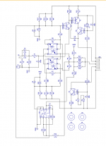
Experimented with the diamond at the input and current drive in VAS stage - started with a single-ended, but then came to symmetric again:
VZ-X CFA front-end
Simulated with both lateral FET and BJT-based NS-OPS - slightly different compensation, but excellent performance in both cases. Well, with NS-OPS distortion is lower by an order or so, but the lateral FETs arrangement attracts with simplicity, still maintaining an excellent performance.
- Status
- Not open for further replies.
- Home
- Amplifiers
- Solid State
- VAS - Symmetric push-pull vs Single-ended + CCS