Hello community,
I'm trying to improve my power amp's VAS using both a so-called "Beta enhancer" and a cascode.
I could understand a little bit the idea behind the emitter-follower (aka Beta enhancer) and could basically dimension it. But I still have difficulties understanding and managing the cascode.
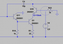
For me, cascode was simply a combination of a Common-emitter and Common-base configuration, i.e. here . So I would connect the base of the cascode transistor with the ground. But I see, all popular designs set a bias at the base of the cascode. I don't understand the idea behind it and cannot reconstruct such a topology in my simulations.
I.e. Bob cordell sets a Bias voltage of 2,5V relative to the negative rail and grounds the base with a 33k resistor. When I try to reconstruct it without capacitor, just like he did it) , the cascode base stays at a constant voltage and nothing swings, see my circuit (See the dashed circle).
Where am I doing/thinking wrong? Could anyone help me?
I'm trying to improve my power amp's VAS using both a so-called "Beta enhancer" and a cascode.
I could understand a little bit the idea behind the emitter-follower (aka Beta enhancer) and could basically dimension it. But I still have difficulties understanding and managing the cascode.
For me, cascode was simply a combination of a Common-emitter and Common-base configuration, i.e. here . So I would connect the base of the cascode transistor with the ground. But I see, all popular designs set a bias at the base of the cascode. I don't understand the idea behind it and cannot reconstruct such a topology in my simulations.
I.e. Bob cordell sets a Bias voltage of 2,5V relative to the negative rail and grounds the base with a 33k resistor. When I try to reconstruct it without capacitor, just like he did it) , the cascode base stays at a constant voltage and nothing swings, see my circuit (See the dashed circle).
Where am I doing/thinking wrong? Could anyone help me?
Attachments
Try setting your V4 voltage to equal the rail voltage PLUS an additional 2.5 volts. So if you are using -/+40 then set V4 to 42.5 volts. Omit your resistor and set V4 to have a series resistance of say 10k.
Try that.
Try that.
The collector of Q18 is undefined in your circuit. It would normally connect to some other circuitry to define the voltage, or would connect to another current source and the sum of the currents at that point would be fed to following circuitry. To test whether your configuration can swing, connect a resistor between the collector and ground.
Ian
Ian
You can't snip just the cascode without showing the rails and the load. It leaves Ian and I in the dark, or at least without something to point-at to show key ideas.
With AC "ground".
But the bottom transistor must have some voltage across it, a few Volts. The upper device's Base then must be few-Volts+0.6V higher for DC, yet unchanging for AC.
Look at a vacuum tube cascode for small signals (TV tuner). The upper device grid is typically run at 1/2 the supply voltage, so both tubes have ample potential. For medium-signal audio (resistor loading), 1/3rd supply has been proposed and will work.
A BJT cascode's bottom device will work at much smaller voltage. And a Vas in a power amplifier needs as much swing on the upper device as it can get. Mooly's values are (of course) a good starting point.
...So I would connect the base of the cascode transistor with the ground....
With AC "ground".
But the bottom transistor must have some voltage across it, a few Volts. The upper device's Base then must be few-Volts+0.6V higher for DC, yet unchanging for AC.
Look at a vacuum tube cascode for small signals (TV tuner). The upper device grid is typically run at 1/2 the supply voltage, so both tubes have ample potential. For medium-signal audio (resistor loading), 1/3rd supply has been proposed and will work.
A BJT cascode's bottom device will work at much smaller voltage. And a Vas in a power amplifier needs as much swing on the upper device as it can get. Mooly's values are (of course) a good starting point.
Thank you very much for your replies!
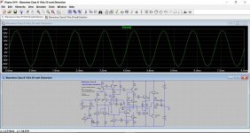
I tried that and set the base voltage to 44.5V. It works indeed but I don't understand why this is good... Now I have a swing from about +2V to -20V at the collector of cascode BJT.
Well, this makes a little sense for me. But what exactly is my AC ground? I supposed, this is the collector of my cascode? So, I set the base voltage to 2.5 from the collector the base. This works too. And I have a balanced swing about 0V in both positive and negative direction. Would it be the correct way to design it?
I also don't understand, why Bob Cordell added a big resistor to the ground in his book...Why is this good?
Try setting your V4 voltage to equal the rail voltage PLUS an additional 2.5 volts. So if you are using -/+40 then set V4 to 42.5 volts. Omit your resistor and set V4 to have a series resistance of say 10k.
Try that.
I tried that and set the base voltage to 44.5V. It works indeed but I don't understand why this is good... Now I have a swing from about +2V to -20V at the collector of cascode BJT.
PRR said:With AC "ground".
But the bottom transistor must have some voltage across it, a few Volts. The upper device's Base then must be few-Volts+0.6V higher for DC, yet unchanging for AC.
Well, this makes a little sense for me. But what exactly is my AC ground? I supposed, this is the collector of my cascode? So, I set the base voltage to 2.5 from the collector the base. This works too. And I have a balanced swing about 0V in both positive and negative direction. Would it be the correct way to design it?
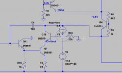
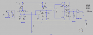
Sorry for that. I attached a screenshot of my whole design.You can't snip just the cascode without showing the rails and the load. It leaves Ian and I in the dark, or at least without something to point-at to show key ideas.
I also don't understand, why Bob Cordell added a big resistor to the ground in his book...Why is this good?
Attachments
Last edited:
You are using a SPICE voltage source, which will maintain whatever voltage you set between its two terminals no matter what.
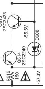
In real life of course, things are different. The voltage used in a cascode is typically defined by a diode drop of some kind e.g. an LED, or a zener diode. These need some current to flow through them in order to work. The resistor to ground produces this current flow.
If you want to try something like this out in SPICE, use e.g. an LED model - I usually use the "QTLP690C" model for this. If you are using Cordell's spice model set, he has a "GREEN" LED model. That should give about 2V drop across it.
Thank you very much for your replies!
I tried that and set the base voltage to 44.5V. It works indeed but I don't understand why this is good... Now I have a swing from about +2V to -20V at the collector of cascode BJT.
Now we can see your circuit I think that Jaycees suggestion should work well.
Here it is added to Doug Selfs design.
Attachments
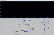
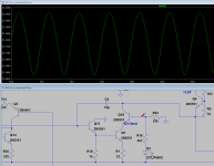
Thank you for your suggestions. I tried them but I don't get the results I expect with them. When I add a voltage drop via diode about 2.5V, it's simply not enough. It only works when I add an additional resistor in series greater than 2k which means an additional voltage drop about 7-8V, thus in total about 10V from negative rail instead of only 2.5V.
Yes, I can play with the values in order to get it work but I don't understand the idea behind that if it doesn't work with a base voltage >V_BE
What are exactly the criteria to design a cascode with? According to which parameter shall I optimize it? Cascode base current? Voltage range at cascode base?
Attachments
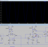
Connecting the cathode of the LED to R1, and avoid the 4,7kohm resistor?
Sajti
It works, too. It works also connecting the LED to cascode's emitter.
But why?
One point to be careful about is that a Darlington feeding a cascode CE stage can sometimes latch. This occurs when the first stage transistor can conduct so much current that the cascode reverse biases. Then your output rail sticks at -Vcc.
To avoid this the current in the first transistor needs to be limited. A 4.7k or 10k resistor will usually work, in the collector, though using an emitter resistor in the CE cascode should help to stop this problem, so this may not be relevant because you have a 22 ohm resistor, but it is something to be aware of.
If the resistor affects the frequency response unduly a small cap can be used to bypass it, but with Miller compensation it is unlikely.
- Status
- Not open for further replies.
- Home
- Amplifiers
- Solid State
- VAS: Emitter-follower and cascode topology/dimensioning