I select some pairs of 2N3773 for quad 405 new boards.
Initialy, I thought of using Moto for a set of two boards, and ON for another set of two board. (comparaison purpose)
Old 2N3773's from motorola
Hfe 10uA, 1mA, 10mA
0, 38, 75
New ON's ones
Hfe 10uA, 1mA, 10mA
53, 199, 115
Amplification differences between 1980 and 2018 transistors can be understood. Old curve is linear, ON have gain fall. Any opinion ?
Your Hfe figures do not look consistent. I am not talking about absolute values, but the relative variations with Ic: the gain normally does droop at high and low currents but for the older version, Hfe falling to zero at 10µA looks too extreme.
It would suggest a poor control of the process, something Moto should have well mastered in 1980.
The ON ones peaking at 1mA look equally suspicious: for such large transistors, the peak should be 1 ~ 2 order of magnitude higher.
This begs the question: how did you make the measurements?
I am not saying they are impossible, and I will search my drawers to find samples if possible, to duplicate your tests, but I smell a rat
Unless that is base current instead of collector current. The 10uA still looks fishy, unless the transistor is leaky. That would make some sort of ‘delta’ measurement inconclusive.
This begs the question: how did you make the measurements?
I use a new DY294 transistor tester with 6V power supply. Transitors was sourced directly from moto and ON
Testing more parts :
Attachments

Last edited:
The DIY294 tester uses mixed Ib/Ic conditions for testing, which is not ideal for consistency: at low currents, it's constant Ib, and at higher currents constant Ic.
I couldn't find 2N3773's in my stash (for the moment), but I found 2N3771 and 72, which are basically the same, except for the voltage selection.
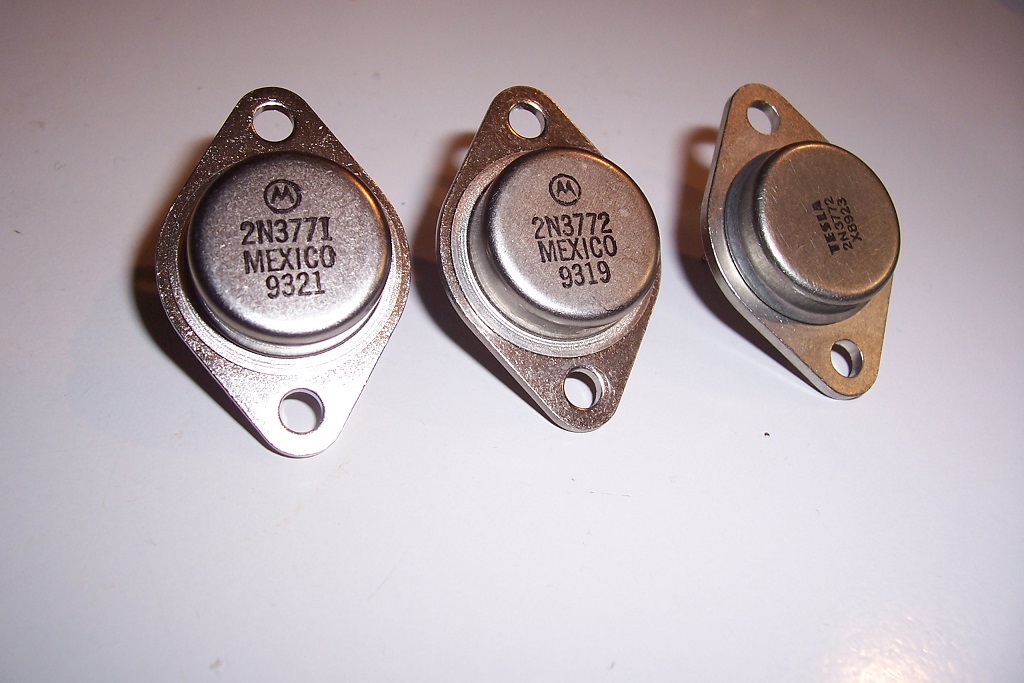
In principle, the beta should drop with increasing Vceo, but the samples I found didn't conform to the rule, which is not surprising: in 1993 the process was more than mature, and the marking simply adapted to the market needs.
I also found a Tesla one, which can be used as an example of a dodgy second source.
Measurements were made at Vce=5V:
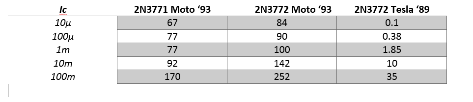
The two Moto samples are quite consistent, even at a 10µA Ic current (which would be ~100nA Ib on your tester if the scale existed)
Of course, my samples were made in 1993, not 1980, but I find it hard to believe that Moto wasn't able to properly control their processes at that time.
Your full data show a more complete picture though, and the values look plausible, even if they are surprising.
By contrast, the Tesla sample has no gain at all under 1mA and rises slowly afterwards.
This points to a poor process control, leading to high internal/leakage currents.
It does however comply with the guaranteed values of the datasheet.
It also has a funny peculiarity: I also tested the Ft, because there was a recent thread on the subject, and it comes out at a surprising 12MHz.
Here is the Ft thread:
2N3773 Frequency transition
I couldn't find 2N3773's in my stash (for the moment), but I found 2N3771 and 72, which are basically the same, except for the voltage selection.
In principle, the beta should drop with increasing Vceo, but the samples I found didn't conform to the rule, which is not surprising: in 1993 the process was more than mature, and the marking simply adapted to the market needs.
I also found a Tesla one, which can be used as an example of a dodgy second source.
Measurements were made at Vce=5V:
The two Moto samples are quite consistent, even at a 10µA Ic current (which would be ~100nA Ib on your tester if the scale existed)
Of course, my samples were made in 1993, not 1980, but I find it hard to believe that Moto wasn't able to properly control their processes at that time.
Your full data show a more complete picture though, and the values look plausible, even if they are surprising.
By contrast, the Tesla sample has no gain at all under 1mA and rises slowly afterwards.
This points to a poor process control, leading to high internal/leakage currents.
It does however comply with the guaranteed values of the datasheet.
It also has a funny peculiarity: I also tested the Ft, because there was a recent thread on the subject, and it comes out at a surprising 12MHz.
Here is the Ft thread:
2N3773 Frequency transition
Attachments


Very consistent answer with multiples thinking axes. 
You recall me that even simple instruments (multimeters...) may need attention as scopes or others.
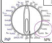
You said : "DIY294 tester uses mixed Ib/Ic conditions for testing." Where did you found this technical information ? I only have simple manual 🙁
In yours tests, values grow up with increasing current. With DIY294,it seems that all transistors showing values over 100 at 1mA will display regressing values on 10mA step. Is it due to "mixed Ib/Ic" method or malfunction ? I will also appreciate owners feedbacks...
You recall me that even simple instruments (multimeters...) may need attention as scopes or others.
You said : "DIY294 tester uses mixed Ib/Ic conditions for testing." Where did you found this technical information ? I only have simple manual 🙁
In yours tests, values grow up with increasing current. With DIY294,it seems that all transistors showing values over 100 at 1mA will display regressing values on 10mA step. Is it due to "mixed Ib/Ic" method or malfunction ? I will also appreciate owners feedbacks...
I searched for a pic of the instrument on the web, and looked at the front panel: Ib and Ic scales are indicatedYou said : "DIY294 tester uses mixed Ib/Ic conditions for testing." Where did you found this technical information ? I only have simple manual 🙁
That's a normal behavior for an oldish, largish transistor like the 2N377x.In yours tests, values grow up with increasing current.
More modern types are flatter, especially in the low-current region
It depends which 10mA you opted for: both Ib and Ic are available, and the actual Ic current (the one that really counts) will have ~the β between them, which is huge (about 100 for the 2N377x).With DIY294,it seems that all transistors showing values over 100 at 1mA will display regressing values on 10mA step. Is it due to "mixed Ib/Ic" method or malfunction ? I will also appreciate owners feedbacks...
Since this transistor is going to peak at hundreds of mA, if not amperes, it explains the difference.
Whenever possible, you should always try to remain on the same constant parameter, preferably Ic for consistency.
At low currents, use Ib, but with high Hfe types, it could result in large Ic.
It is a cheap, simplified tester, and you have to live with its shortcomings or upgrade....
It should be possible to find historic Hfe/Ic curves on the net for this transistor, but I ran out of patience.
They should show where the gain peaks (I would guess around 1A).
ONsemi data pertain to a more modern process, and are flatter (as my tests show)
They should show where the gain peaks (I would guess around 1A).
ONsemi data pertain to a more modern process, and are flatter (as my tests show)
....I ran out of patience.
...modern process, and are flatter...
My 1966 RCA book has very limited data, nothing below 50mA; basically giving a minimum hFE for HIGH currents. (If you want small currents, why buy a 16A part??) It does show open-emitter base current of several mA, which will spill the curves at low current.
RCA SC12: http://www.rsp-italy.it/Electronics/Databooks/RCA/_contents/RCA Transistor Manual SC12 1966.pdf 38MB PDF, after page 256
Farnell posted data for a 2N3773 (and PNP twin) which is indeed new-style.
http://www.farnell.com/datasheets/313201.pdf
Attachments
- Home
- Design & Build
- Parts
- Variations on 2N3773