If one wants to fuse protect the output, then put a fuse in the output.Ok lest start with this.
Now assume the wiper is set at 10% ..output voltage will be 1/10 of input voltage & output current will be 10 times input current. so if output current should not go above 3.25 amp input curent will be 0.32amp.
Then if the wiper is set at 80% ..output voltage will be 8/10 of input voltage & output current will be 1.25 times input current. so if output current should not go above 3.25 amp input current will be 2.6amp.
Output current is should not go above rated current but input current is depandant of the ratio, if you change the ratio maximum output current is still the same but input current will change.
Putting the fuse at the input will protec only one part of the winding but will not protect the wiper.
To protect the wiper ( the most critical part of the variac ) fuse must be in the wiper.
If one wants to protect the house/dwelling/workshop, then put a fuse in the primary.
It depends on why one uses a fuse and what one can expect from that fuse.
A fuse in the wiper lead may not rupture until 1kA has passed for 100us. Will a fuse protect the wiper?
or stop the house burning down?
No. One puts the fuse in the primary to stop the house burning down. Adding a fuse to the wiper lead does not protect the wiper. A wiper lead fuse protects the output wire from setting fire to it's surroundings.
Last edited:
I never said that the fuse at the input should be removed ....
I only explain that there should be a fuse at the wiper otherwise the wiper may have a destructive overcurrent.
I only explain that there should be a fuse at the wiper otherwise the wiper may have a destructive overcurrent.
Short circuit in electronic will blow a transistor in less time than a usual fuse will take to blow.
For a variac a well selected fuse will blow before you have damage to the variac, a variac is a special form of transformer ... has some inductance in the winding ans is quite slow if you compare to a transistor circuit.
For a variac a well selected fuse will blow before you have damage to the variac, a variac is a special form of transformer ... has some inductance in the winding ans is quite slow if you compare to a transistor circuit.
The transformer core and the transformer windings do indeed have an enormous capacity to tolerate overload.
But you have been talking about protecting the wiper.
I don't have much idea of the wiper's tolerance to overload.
You seem to think it needs protecting. That implies that you think it has a low tolerance to overload.
A fuse is NOT there to protect down stream components from being damaged during some other fault.
The fuse is NOT there to stop some upstream component from being damaged during some other fault.
A fuse is there to stop the system setting fire to the surroundings during a fault.
Since I found a decent lab power supply (2 x 65V, 0 - 4A) and a smaller one (2 x 30V, 0 - 3A) and a light bulb circuit and an Earth Fault Protection Circuit on front of everything I never ever used the variac again That's for 20 years now.
Agree, it's some money to be spend for these supplies, but it's money wel spent.
Tube equipment: Bulb and if it shines brightly; isolate the secundary of the psu from the primary. Still a lot of light; check the wiring, tranfsformer, the usual stuff.
If no light, connect the Bench psu to the circuit after setting the wanted voltages and max current. Then proceed with the repair.
Same same for solid state equipment.
Simple, efficient, and no burned parts anymore.
But as said, a bit more costly then a variac.
I did work with students for 30 years ... I saw many mistakes ... belive me a fuse in the wiper is the thing to do . Wiper will have a very efficient protection and you will save bucks ...
A man can not have to many a Variacs.
Got a tiny 200VA, but never use it.
Got a fully isolated 750VA with amp and voltage meter. Power cord has a soft start box attached permanently. Got a 3,5A resetable fues.
This is an indispensible tool.
Got a normal 10A Variac too, using external soft start.
Got a light bulb tester with up to 4 light bulbs parallelled with normal power cord socket in/out.
I live in 50Hz/230VAC land.
My house has all through Earth Fault Circuit on all appliances with a fixed installation and power outlets.
And why do you think you are the only audience here? T
Back at you.
My OP on this topic was presented as an alternative viewpoint,
Read it, it says so in plain English right up front,
Since you obviously read and perceive perfectly the obvious conclusion is that it issomehow wrong to express alternative ideas. If that is in the TOS, please advise.
"Use the force Luke - let go..."
Never throw caution to the wind - there is no better reflection of delta, than a good old analog meter. As far as protection goes, I don't care how long you've been doing this - if you don't utilize all available protection, as close to the stored energy as possible, you are not only foolish, but also have no business giving advice to anyone else on the subject.
Mains Cutoff - Toggle Switch/E-Stop
Isolation Transformer
Current Limiting - Dim Bulb/Inline Circuit Breaker/Mains Fuse
Visual Feedback - Amp Meter/Indicator Bulb (Volt Meter = Useless)
Anything short of that, is akin to saying, "Hold my beer, and watch this..."
Out here in the professional world, people with the "I got this" attitude, are either retired, unemployed, or dead.
Attachments
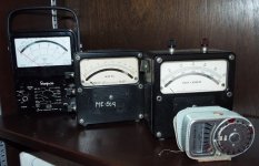
I am a 'Variac Virgin' and got mine only yesterday. Until now, I've been using a self-built dim bulb tester. I will be building it into a steel enclosure and it will have analogue volt and ampere meters (if I can get them). If not, will digital meters do?
Another thing I'd like to change will be that metal knob to a large dia bakelite item.
Pics to follow
bulgin
Another thing I'd like to change will be that metal knob to a large dia bakelite item.
Pics to follow
bulgin
Attachments

Last edited:
For sure, that knob is really uncool on the variac.
Digital meters work, but analog meters are much easier to follow trends on. particularly the current.
Digital meters work, but analog meters are much easier to follow trends on. particularly the current.
I am a 'Variac Virgin' and got mine only yesterday. Until now, I've been using a self-built dim bulb tester.
I wouldn't quit using it either.
Hi Guys
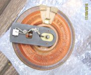
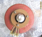
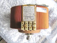
Anyone care to indicate where current goes in and current out on the connector blocks? I'm aware of the dangers using variacs and will not use it or connect it to ac before getting more advice, building it into a metal enclosure, fused and with an on/off switch.
Thanks
bulgin
Anyone care to indicate where current goes in and current out on the connector blocks? I'm aware of the dangers using variacs and will not use it or connect it to ac before getting more advice, building it into a metal enclosure, fused and with an on/off switch.
Thanks
bulgin
Bulgin,
K- Neutral in and out ( Blue wire from source )
N- Live in ( Brown wire from source)
T- Live out from wiper ( Output)
This is for South African wiring standards only.
K- Neutral in and out ( Blue wire from source )
N- Live in ( Brown wire from source)
T- Live out from wiper ( Output)
This is for South African wiring standards only.
Last edited:

Bulgin,
K- Neutral in and out ( Blue wire from source )
N- Live in ( Brown wire from source)
T- Live out from wiper ( Output)
This is for South African wiring standards only.
Hello Jan
Thank you🙂 Much obliged. I'm gathering as much information as possible before I start building it into an enclosure.
Regards
bulgin
Hello Guys
This is bulgin's wife writing. bulgin....
Caught ya, didn't I?😀
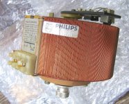
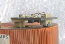
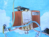
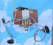
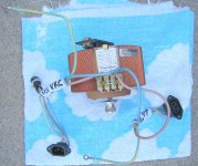
Following Jan's (Vrystaat's) explanation, I wired-up the variac temporarily and I'm writing just to check to find out if I did so correctly. Please note that I will not plug it in or try to use it before it has been built into an enclosure and I'm 100% sure the wiring is correct. I did the job this afternoon and in hindsight, I think I have the 5A fuse soldered incorrectly on the 230VAC live wire IN.
Will it be OK to leave it here and also add a second 5A fuse on the live wire of the current out?
The lefthand loom to the IEC socket is for 230VAC IN and the righthand loom obviously for ac current OUT.
From my pics, you can see there are two earth wires with tags - these will both be bolted to chassis ground??
The next steps (if my wiring is correct) will be to source a steel or aluminium enclosure and I have someone looking for me to find a 230VAC analogue volt meter.
Thanks for your kind advices.
bulgin
This is bulgin's wife writing. bulgin....
Caught ya, didn't I?😀
Following Jan's (Vrystaat's) explanation, I wired-up the variac temporarily and I'm writing just to check to find out if I did so correctly. Please note that I will not plug it in or try to use it before it has been built into an enclosure and I'm 100% sure the wiring is correct. I did the job this afternoon and in hindsight, I think I have the 5A fuse soldered incorrectly on the 230VAC live wire IN.
Will it be OK to leave it here and also add a second 5A fuse on the live wire of the current out?
The lefthand loom to the IEC socket is for 230VAC IN and the righthand loom obviously for ac current OUT.
From my pics, you can see there are two earth wires with tags - these will both be bolted to chassis ground??
The next steps (if my wiring is correct) will be to source a steel or aluminium enclosure and I have someone looking for me to find a 230VAC analogue volt meter.
Thanks for your kind advices.
bulgin
Attachments
Last edited:
- Status
- Not open for further replies.
- Home
- Design & Build
- Equipment & Tools
- Variac: what should I add when putting it in an enclosure?