It seems difficult and/or quite expensive to find a symmetric DC power supply capable of adjustable rails of up about 70 Volts DC capable of delivering about 5-6 amps.
In my possession, I already have a:
- 1000 VA toroidal transformer (120/240 VAC -> 2 x 50VAC).
- dual gang 40 VAC -> 40 VAC 10 amp variac (Powerstat 116CU-40-2)
- 160 amp rectifier
- about 200,000uF @ 200 volt electrolytics.
So I decided to do the following, please indicate if you see any flaw with it.
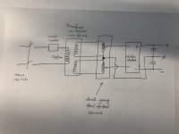
The idea is to feed the 50 volts from each secondary of the transformer to the 40 V inputs of the dual gang variac. The outputs are rectified and filtered and I get a very powerful (with very little ripple) power supply of up to about +/- 70 volts DC at about 10 amps max.
One issue I am thinking is that specific variac is specced to run at 60Hz. If I move this to a 50Hz country, I presume the max current rating will probably be less but does anyone see any other issue ?
I am adding a picture here:
In my possession, I already have a:
- 1000 VA toroidal transformer (120/240 VAC -> 2 x 50VAC).
- dual gang 40 VAC -> 40 VAC 10 amp variac (Powerstat 116CU-40-2)
- 160 amp rectifier
- about 200,000uF @ 200 volt electrolytics.
So I decided to do the following, please indicate if you see any flaw with it.
The idea is to feed the 50 volts from each secondary of the transformer to the 40 V inputs of the dual gang variac. The outputs are rectified and filtered and I get a very powerful (with very little ripple) power supply of up to about +/- 70 volts DC at about 10 amps max.
One issue I am thinking is that specific variac is specced to run at 60Hz. If I move this to a 50Hz country, I presume the max current rating will probably be less but does anyone see any other issue ?
I am adding a picture here:
Attachments
Last edited:
Yes, it is Powerstat 116CU-40-2
I updated the above with this info and also have the following q:
That specific variac is specced to run at 60Hz. If I move this to a 50Hz country, I presume the max current rating will probably be less but does anyone see any other issue ?
Thanks
I updated the above with this info and also have the following q:
That specific variac is specced to run at 60Hz. If I move this to a 50Hz country, I presume the max current rating will probably be less but does anyone see any other issue ?
Thanks
Last edited:
I think that should be OK provided the outputs of the variac are wired the right way around. Powerstat list a new model for that 116cu-*-2 design and link it to this drawing:
An externally hosted image should be here but it was not working when we last tested it.
I'm afraid this will not work. Your voltage is 20% too high and the frequency 20% less. The variac will saturate and also the mains transformer, probably blowing your mains fuse.
You wouldn't be able to draw 10 amps continuously, but I think 5-6 would be within the capability of the gear even at the wrong mains frequency and over-voltage input. These things are pretty rugged.
How much can I overload my Variac and for how long?
https://variac.com/ShortTermOverload.pdf?_ga=2.140403830.492649155.1627083906-1433848266.1627083906
How much can I overload my Variac and for how long?
https://variac.com/ShortTermOverload.pdf?_ga=2.140403830.492649155.1627083906-1433848266.1627083906
Hi Bansuri,
The transformer is suitable for 50 or 60 Hz, so it does not have any issues. My only concern was the variac but as johnmath mentioned, those devices are built like tanks. 20% voltage overload is pretty much nothing to it.
The transformer is suitable for 50 or 60 Hz, so it does not have any issues. My only concern was the variac but as johnmath mentioned, those devices are built like tanks. 20% voltage overload is pretty much nothing to it.
that is not true, only 60Hz. the motor is rated for 50 and 60Hz but not the transformer.
http://www.farnell.com/datasheets/162537.pdf
The saturation occurs when switching on, even without load, maybe your soft start can prevent that
connect the 2 transformers and look what happens, before you put it all together
http://www.farnell.com/datasheets/162537.pdf
The saturation occurs when switching on, even without load, maybe your soft start can prevent that
connect the 2 transformers and look what happens, before you put it all together
Last edited:
I use similar setup for testing new stuff, adding a rotary switch or relays to to let the rail go through power resistors to set a maximum current draw, also a light bulb and fuses could be nice addition
Another alternative could be that I have a 120 volt -> 120 volt variac first in the system feeding the toroidal txformer. In this case, I would not need a dual gang variac. A single gang would do.
However, my question now is, (this is also a general question) if I feed the toroidal a primary voltage which is much less than its rated voltage, would its secondary still linearly follow the turns ratio or would it not generate any secondary until some 'threshold' would be reached ? If so, this would be like a 'step' jump and would not be a truly variable power supply...
Thanks
No there's no threshold. Same as an audio transformer. Small signals come through in exact proportion.
Anyway you are going to monitor the output voltage, right? You can allow for any unlikely "jump".
Anyway you are going to monitor the output voltage, right? You can allow for any unlikely "jump".
Hi PRR,
Thanks for your answer & yes, I will have a voltmeter & an ammeter on BOTH rails to notice any anomalies.
I will therefore switch to the single gang variac since it will save me a lot of weight & space.
Thanks for your answer & yes, I will have a voltmeter & an ammeter on BOTH rails to notice any anomalies.
I will therefore switch to the single gang variac since it will save me a lot of weight & space.
Is this just for bench testing of some kind?
In a typical power supply (ie. without the variac) the source impedance before the rectifier will be lower (as there is no additional series impedance from the variac) and so the rectification current waveform and capacitor ripple may be slightly different.
In a typical power supply (ie. without the variac) the source impedance before the rectifier will be lower (as there is no additional series impedance from the variac) and so the rectification current waveform and capacitor ripple may be slightly different.
Hi trobbins,
Yes, this is for bench testing.
I may switch to a single gang variac ( Powerstat 217CU) (120/240 volt, 3.5A) and since I have about 200,000 uF of capacitance after the rectifiers, I do not think ripple will be an issue. Altho, I see conflicting information online regarding either 216CU or the 217CU models. Some literature says they can operate at 50 Hz and some limit it to only 60 Hz. So, I am not sure as to which is the correct value.
Last edited:
I don't think it is a matter of right or wrong, rather the specification rating quoted is at the frequency quoted, kind of like (but not exactly the same as) an amplifier's power being rated into a specified load, e.g. 4Ω or 8Ω.Some literature says they can operate at 50 Hz and some limit it to only 60 Hz. So, I am not sure as to which is the correct value.
- Home
- Amplifiers
- Power Supplies
- variac based symmetric bench power supply