The unbypassed cathode will indeed help to reduce the open-loop distortion a bit. Not much. It will probably still be very 'tube sounding' which may or may not be what you want.
The datasheet says it should be able to be used as an AF amplifier, strangely enough. This was just a quick and dirty calculation and it's at the very limit for screen dissipation. That is if I've done it correctly 🙂
I could try using the component values for AF use in the datasheet, it should be able to get down to 0.8% distortion but with way too much gain. With negative control voltage on the grid the gain should be reduced a bit, could I just use a battery for this?
I could try using the component values for AF use in the datasheet, it should be able to get down to 0.8% distortion but with way too much gain. With negative control voltage on the grid the gain should be reduced a bit, could I just use a battery for this?
Last edited:
@showdown - "With negative control voltage on the grid the gain should be reduced a bit, could I just use a battery for this? "
Cant you just increase the cathode resistor value to achieve it? Right up into Cathodyne levels? I dont know much about tube design either, but that seems doable -
Cant you just increase the cathode resistor value to achieve it? Right up into Cathodyne levels? I dont know much about tube design either, but that seems doable -
Cant you just increase the cathode resistor value to achieve it? Right up into Cathodyne levels? I dont know much about tube design either, but that seems doable -
Well, that's a bit unclear to me: "The control voltage on the grid must not be interchanged with the grid bias, which consists of the control voltage augmented by the voltage drop across the cathode resistor."
So it seems I need a negative supply on the grid in addition to the cathode resistor if I understand it correctly?
The 0.8% THD in the philips data sheet is valid for very low input signals only. Here it says 75mV RMS max input for 3V RMS output. Anything above that and distortion rises sharply.
The more negative the grid gets with respect to the cathode the higher the distortion. So reducing gain by increasing negative grid bias is counter productive.
By the way, the EF9 data sheet proposes to use gliding screen voltage, i.e. a 800 kohm non bypassed screen resistor, which acts as a kind of negative feedback: rising plate current causes rising screen current which in turn tries to lower plate current. This FB mechanism cannot work with zener stabilisation ...
Most remote cutoffs can be used as AF amplifiers with moderate distortion when signal levels are kept low in the mVs and negative grid voltages also low around 1 V.
If you want lower gain, you should consider triode connection. Another ingenious way to implement negative feedback by screen ...
Last edited:
No, it's talking about "AF amplifier with controlled amplification", i.e. electronic gain control. But you're building a simple fixed gain stage, no grid control voltage is needed.Well, that's a bit unclear to me: "The control voltage on the grid must not be interchanged with the grid bias, which consists of the control voltage augmented by the voltage drop across the cathode resistor."
So it seems I need a negative supply on the grid in addition to the cathode resistor if I understand it correctly?
(also, it helps to provide the link so others can answer you)
Good thing I didn’t get my hopes up for this tube, it was more of a design exercise because I have a couple in a box 🙂 I guess it’s just not suited for a line preamp, it doesn’t make much sense to have to attenuate the input signal just so it can be amplified cleanly. But they do look nice 🙂
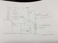
I don't think IA will be 7 mA. Ohm's Law:
⋅-⋅-⋅ Just saying, ⋅-⋅-⋅
⋅-=≡ GoatGuy ✓ ≡=-⋅
E = I R
E = ⁷⁄₁₀₀₀ A × 47,000 Ω
E = 328 V …
Which is substantially greater than the B+ of 250 V. Yah know? E = ⁷⁄₁₀₀₀ A × 47,000 Ω
E = 328 V …
⋅-⋅-⋅ Just saying, ⋅-⋅-⋅
⋅-=≡ GoatGuy ✓ ≡=-⋅
Secondarily, if you really want to 'tame' the valve, i would think having a constant-current load would be “the trick”. Turn the thing into a μ (Mu) controlled amplifier, which has a lot less variation, methinks. Dunno. I'd at least breadboard it. ⋅-=≡ GoatGuy ✓ ≡=-⋅
I could try using the component values for AF use in the datasheet, it should be able to get down to 0.8% distortion but with way too much gain.
Try EF89 connected as triode. Gain drops to some 15...21 dB depending on the Rk.
Low output impedance and "adjustable sound" with Rk (150 ohms to 1k).
THD is lower than as pentode.
Attachments

@Sorento - "The more negative the grid gets with respect to the cathode the higher the distortion." Really? So there's a sweet spot because certainly if you drive the grid positive...
@Showdown - sorry if I only confused you further. Generally the DC drop across the cathode resistor sets the quiescent grid bias, so I was thinking just make that drop larger, versus a battery...
I think the ideas presented on doing a triode connection and using a constant current circuit are good. For making a good lookin' bottle perform well enough to be included in your signal chain!
I'd bet there's many tube types that fall into such a category; look awesome - and with a little help from their solid state friends, along with some clever engineering!
@Sorento - "The more negative the grid gets with respect to the cathode the higher the distortion." Really? So there's a sweet spot because certainly if you drive the grid positive...
And isn't it that what the plate curves of a remote cutoff suggest, which get more and more compressed with higher negative grid ? and this tube makes no exception.
The Philips data sheet also shows this in that big table:
Vg1= 0 THD=0.8 Gain=106
Vg1=-5 THD=0.8 Gain=40
Vg1=-10 THD=1.1 Gain=23
Vg1=-18 THD=1.5 Gain=11
Vg1=-25 THD=2.7 Gain=6
So the sweet spot seems to be between 0 and -5 and judging from the plate curves might be closer to 0 than to -5 ...
I’ve never messed with any of that newfangled CCS stuff before but this could be an excuse to start... I’ll have to read up a bit and look at my options. It seems like that’s the way to go, I’m a big fan of making things work where they shouldn’t, so it could be worth a shot 🙂
I’ve seen triode connections with g2 to the anode and g3 to the cathode, as well as some with both g2 and g3 connected to the anode. Not sure what would be best with this tube.
I’ve seen triode connections with g2 to the anode and g3 to the cathode, as well as some with both g2 and g3 connected to the anode. Not sure what would be best with this tube.
Just that CCS load boosts gain to its max for a given tube, I thought you wanted less ...
G3 doesn't really matter in triode mode, connect to plate or cathode, works either way.
Triode connection not only lowers gain, lowers THD, but has lower output impedance, too.
For pre-amp service Pentode connected plus CCS load will undoubtedly require a cathode follower - another tube - to drive a power amp, especially if there is a cable in between. With Triode connection you might get away without.
By the way, nothing prevents you from using another EF9 as a follower ...
The 100% local feedback of a CF should swamp any nonlinearities of the tube anyway.
Last edited:
No essential difference. Connect a, g2 and g3 together. Cathode resistor adjustment has much bigger effect to THD and gain.
For pre-amp service Pentode connected plus CCS load will undoubtedly require a cathode follower
Running a pentode into a CCS load makes for ridiculous amounts of gain. I have a little guitar amp running a 18FW6 (like a 6AU6) into a CCS with a pot across the CCS for variable gain. With the pot at max (2 meg) I get gain in the 1000 X range. With that kind of voltage gain the tube is highly microphonic.
If you want to play with a CCS, triode wire the tube.
g3 to the cathode, as well as some with both g2 and g3 connected to the anode. Not sure what would be best with this tube.……..G3 doesn't really matter in triode mode
I don't know anything about this particular tube, but the G3 connection often affects the distortion a bit, even in triode. Try it both ways.
Running a pentode into a CCS load makes for ridiculous amounts of gain. I have a little guitar amp running a 18FW6 (like a 6AU6) into a CCS with a pot across the CCS for variable gain. With the pot at max (2 meg) I get gain in the 1000× range. With that kind of voltage gain the tube is highly microphonic.
If you want to play with a CCS, triode wire the tube.
I don't know anything about this particular tube, but the G3 connection often affects the distortion a bit, even in triode. Try it both ways.
Yes, that too is true. However, consider … the usual “taming” maneuvers.
“Zeroth”, as you say, wire for triode instead of pentode. That'll reduce gain by at least ¹⁄₁₀. At least. (zero = your solution)
First, a R+C series resistor from anode back to control grid. Have to look at the control grid ballast resistor, consider it as a voltage divider 'lower end'.
Say the ballast is 47 kΩ. Tying 10× that, in this case a 470 kΩ resistor ⊕ 0.22 µF 350 V capacitor from anode back to ballasted grid ties 10% of the gain as NFB. That'll really linearize the valve, as well as again taming gain. Virtually kills microphonics.
Second, use another load-divider to cut output by a similar ratio, cutting both amplification noise, amplification microphonics and all the rest. It sturdies up the output impedance without loading the valve substantially. Another 470 kΩ in series with 47 kΩ to drop gain to ¹⁄₁₀th of the residual given № 1.
Load to pentode would be 517 kΩ. Impedance to output is 470 || 47 = 42 kΩ. Microphonics, –20 dB.
Just saying, goats… there are a lot of creative ways to substantially linearize the hot-mess of a variable mu valve, whilst delivering otherwise auspicious results.
⋅-=≡ GoatGuy ✓ ≡=-⋅
Datasheet curves page 3 show the maximum clean input; about 280mV at full gain. This is for RF tuned-circuit; the Audio max will be less.
It may help to understand what this tube is for. A consumer audio tape recorder AGC. It is variable-gain, but with sliding-G2 the change of plate current is very small. This means the AGC thump is tolerable (a plain RF/IF vari-tube would thump bad), even in resistor-loaded circuits. The input is a *domestic* microphone, rarely even 10mV. (It may have taken Line in but it would be padded way down.) The output is "line" but not today's 2V 50 Ohm, more like sub-Volt and 200k.
Fool with it if you please, but it has no "good" use in modern hi-fi.
Work smarter, not harder. If you used one EF9 for gain followed by another EF9 as a heavily loaded cathode follower you might be able to use the distortion cancellation to get a good overall figure...
Having said that, the curves on page 5 between Vgk = 0V and vgk = -3V honestly don't look that bad. Not much worse than any normal pentode. With an unbypassed cathode as in your original circuit you'll probably get a useable middle-of-the-road distortion figure, and extra headroom of course. Or you could use it triode-strapped.
Having said that, the curves on page 5 between Vgk = 0V and vgk = -3V honestly don't look that bad. Not much worse than any normal pentode. With an unbypassed cathode as in your original circuit you'll probably get a useable middle-of-the-road distortion figure, and extra headroom of course. Or you could use it triode-strapped.
Last edited:
- Home
- Amplifiers
- Tubes / Valves
- Variable-mu madness