Thinking out loud: for a given phono preamp design, couldn't the accuracy of the RIAA equalization vary significantly with individual tube characteristics, both for passive and feedback type? Although maybe not the case for certain NOS tube types, I was thinking this would almost certainly be the case for the ubiquitous 12AX7 preamp since there are so many variants of the 12AX7 (e.g. long plate vs short plate, NOS vs Russian, etc.).
Just for background, I was researching the idea of making an improved Marantz 7 type phono preamp by putting a tube other than 12AX7 in the first position for lower input capacitance.
Just for background, I was researching the idea of making an improved Marantz 7 type phono preamp by putting a tube other than 12AX7 in the first position for lower input capacitance.
Yes. RIAA accuracy is always affected by the valve type. The only way to (almost) eliminate the variation in a passive type would be to use a cathode follower to drive each network and a cascode after the network. With a feedback network, changing valve characteristics will change the open loop gain and because it's not infinite, that will affect RIAA accuracy.
ECC88/6DJ8 is a favourite input valve.
ECC88/6DJ8 is a favourite input valve.
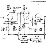
If it is a composite passive RIAA like in the schematic linked below
http://www.geocities.com/rjm003.geo/rjmaudio/diy_pho3.html
Switching to a tube other than a 12ax7, the plate and cathode resistor should be changed to optimize the operating point for the new tube type.
To get back the proper RIAA curve the only value you should have to tweak is the one listed as R5 in the above schematic. The rest of the network values shouldn't have to be changed.
If your new tube has a lower Z-out you will have to increase the value of R5. If it has a higher Z-out you will have to decrease the value of R5.
The idea is to make the eq as independent as possible of what happens to the tube over time or when it's replaced. The cathode follower suggestion of EC8010 is certainly an excellent approach. Another way which is nearly as good is to make the build-out resistor in the RIAA circuit (that's R5 in the schematic Jeb linked to) very large compared to the expected source resistance. If the first stage is run undegenerated grounded-cathode, that will be the plate resistance in parallel with the plate load resistor. If R5 is ten or more times bigger, then the eq will be fairly insensitive to a range of expected tube variations.
The plate resistance of an ECC88, for example, will be something like 3-4k. If we choose 3k5 as a nominal for the sake of illustration, variances of 500 ohms up or down will cause less than 0.05dB of error if the build-out resistor is 100k or so.
The plate resistance of an ECC88, for example, will be something like 3-4k. If we choose 3k5 as a nominal for the sake of illustration, variances of 500 ohms up or down will cause less than 0.05dB of error if the build-out resistor is 100k or so.
The plate resistance of an ECC88, for example, will be something like 3-4k. If we choose 3k5 as a nominal for the sake of illustration, variances of 500 ohms up or down will cause less than 0.05dB of error if the build-out resistor is 100k or so.
Yeah, if he adapts and ECC88 into a circuit designed for a 12AX7. Chances are he will end up with a large build-out resistor by the time the RIAA curve is corrected.
A cathode follower is a good idea if building from scratch (low Cin and Zout), but would probably result in excessive gain loss if adapting it into an existing circuit (that isn't already using one of course).
No, you should be able to minimize the gain loss- after all, an ECC88 CF will have a gain of about 0.97. It's just a pita to shove one into an existing scheme, especially when considering heater-to-cathode voltage issues.
LB,
The Marantz circuit uses filters in a NFB loop to achieve the goal. That's active EQ. In circuits with loop NFB, the feedback network dominates behavior, as long as open loop gain is sufficient.
You said you wanted to use a type with lower Miller capacitance in the 1st gain block. The 6GK5 should fill the requirement. Stage gain will easily be equivalent, even though 6GK5 mu is lower than 12AX7 mu. The 6GK5 is high mu, high gm, and low Rp. The smaller Rp makes up for the lower mu.
The use of a 12AX7 section in cathode follower leaves (IMO) much to be desired. Inside a full function preamp that included at line stage, the 'X7 CF was tolerable. No way is it going to drive both the NFB loop and a downstream external load that includes cable capacitance. Point blank, the 12AX7 is a WIMP. DC couple a ZVN0545A enhancement MOSFET to the 2nd gain triode's anode as the voltage follower. You eliminate a coupling cap. and improve drive capability. Id = 2 mA. should get the job done.
BTW, the O/P coupling cap. needs to be at least 3.3 muF., if you are going to drive the IHF "standard" load of 10 KOhms.
A feedback RIAA is devilishly hard to do properly. It will take a much more complex circuit than that and unless you really know what you're doing, it will be difficult to stabilize and provide adequate overload margins. With all due respect to tradition and my elders, the Marantz phono circuit was mediocre at best.
I'd stick with a simple passive approach.
I'd stick with a simple passive approach.
Maybe a bit off topic, but I described my passive tube RIAA that gives exact equalization in this thread:
http://www.diyaudio.com/forums/showthread.php?s=&threadid=119229
http://www.diyaudio.com/forums/showthread.php?s=&threadid=119229
leadbelly said:Thinking out loud: for a given phono preamp design, couldn't the accuracy of the RIAA equalization vary significantly with individual tube characteristics, both for passive and feedback type? Although maybe not the case for certain NOS tube types, I was thinking this would almost certainly be the case for the ubiquitous 12AX7 preamp since there are so many variants of the 12AX7 (e.g. long plate vs short plate, NOS vs Russian, etc.).
There are lots of other components the accuracy of the RIAA
equalization depends on.
Who cares about the calble capacitance, the input capacitance
of the RIAA preamp the pic up characteristic etc. , needless to
say the loudspeaker.
So why do you want to eliminate the influence of the tube
characteristic completely? Does a tube RIAA preamp make
sense if there is no influence by the tubes in the characteristic
of the preamp?
I decided to give the triodes µ an influence in the
RIAA curve. I like it this way, no semiconductor is able to
make this kind of influence. 🙂
Kind regards,
Darius🙂
Here's an example where the tube has virtually no influence on the RIAA curve. Rp of the cascoded input tube is in the MOhm range with the FET on the bottom: http://www.diyaudio.com/forums/showthread.php?postid=959597#post959597
http://www.diyaudio.com/forums/showthread.php?postid=959687#post959687
Same thing can be done with a tube on the bottom, instead of the FET:
http://members.aol.com/sbench101/Preamps/RIAA5.gif
Sheldon
http://www.diyaudio.com/forums/showthread.php?postid=959687#post959687
Same thing can be done with a tube on the bottom, instead of the FET:
http://members.aol.com/sbench101/Preamps/RIAA5.gif
Sheldon
Who cares about the calble capacitance, the input capacitance
The cable going from the turntable to the pre-amp? The capacitance is very important. If you have ever seen what different capacitance does to a cartridges frequency responce you would probably find it important too. I've measured as much as 320pF on some cables 😱 For a few cartridges this is ok, but for most it's way too much. Especially after you sum it with the input capacitance of the pre-amp.
Does a tube RIAA preamp make
sense if there is no influence by the tubes in the characteristic
of the preamp? I decided to give the triodes µ an influence in the
RIAA curve.
For most, the goal of a tube preamp is to get the tubes tonality influence while still getting the correct RIAA curve.
#13
Hi,
I think we misunderstood,
I care about the cable capacitance.
But there are enthusiasts who wants to get more
than say 0,5dB close to the RIAA curve
and don't see this aspect.
Yes of course I want to be close to the RIAA curve.
Kind regards,
Darius
Hi,
I think we misunderstood,
I care about the cable capacitance.
But there are enthusiasts who wants to get more
than say 0,5dB close to the RIAA curve
and don't see this aspect.
Yes of course I want to be close to the RIAA curve.
Kind regards,
Darius
#12
Hello Sheldon,
I think the (asymmetrical) cathode coupled stage is the
better solution. Even if it is a little bit more noisy.
A cascode kills the triode characteristics.
Cascode is similar to a pentode.
This is why I don't like triodes in cascode arrangements.
Kind regards,
Darius
Hello Sheldon,
I think the (asymmetrical) cathode coupled stage is the
better solution. Even if it is a little bit more noisy.
A cascode kills the triode characteristics.
Cascode is similar to a pentode.
This is why I don't like triodes in cascode arrangements.
Kind regards,
Darius
Re: #12
Which triode characteristic does the cascode kill? The one triode characteristic I'm aware of, that the cascode arrangement kills, is the Miller capacitance. I don't think the plate curves don't all of a sudden become pentode like.
Sheldon
oldeurope said:A cascode kills the triode characteristics.
Cascode is similar to a pentode.
This is why I don't like triodes in cascode arrangements.
Which triode characteristic does the cascode kill? The one triode characteristic I'm aware of, that the cascode arrangement kills, is the Miller capacitance. I don't think the plate curves don't all of a sudden become pentode like.
Sheldon
cascode vs asymmetrical cathode coupled
Kind regards,
Darius
http://www.diyaudio.com/forums/showthread.php?s=&threadid=120740Sheldon said:
Which triode characteristic does the cascode kill? The one triode characteristic I'm aware of, that the cascode arrangement kills, is the Miller capacitance. I don't think the plate curves don't all of a sudden become pentode like.
Sheldon
Kind regards,
Darius
OK, I have a follow up question, does the position of the DC blocking cap in a passive preamp affect the eq?
To explain what I mean, I have attached 2 examples, with the DC blocking caps circled in red. Are the two equivalent, or does placing the cap in front of the passive RIAA components affect the eq?
To explain what I mean, I have attached 2 examples, with the DC blocking caps circled in red. Are the two equivalent, or does placing the cap in front of the passive RIAA components affect the eq?
Attachments
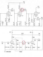
To be sure, place it after the eq. That will also allow you to make it smaller since the input Z of the last stage of your circuit is bootstrapped.
SY said:To be sure, place it after the eq. That will also allow you to make it smaller since the input Z of the last stage of your circuit is bootstrapped.
Geez, that's a problem. What my plan actually is, is to build a preamp with cheap PCB's I got on eBay. The schematic for those PCB's is the upper half of the file I attached. I am thinking I would like to build it as a hybrid, with a JFET replacing the first triode stage, a Russian 6922 for the 2nd stage, and a Russian 6N6P for the CF. So the blocking cap needs to be before the RIAA section.
- Status
- Not open for further replies.
- Home
- Amplifiers
- Tubes / Valves
- Variability of RIAA eq with tube characteristics?