Hello
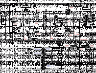
Has some tried to build / hear the attached amplifier. The diagram is from Japanese Valves' world.
I like the simple design and the use of small power tubes as drivers.
I will use 6BG6G as output tubes.
Regards
Benny
Has some tried to build / hear the attached amplifier. The diagram is from Japanese Valves' world.
I like the simple design and the use of small power tubes as drivers.
I will use 6BG6G as output tubes.
Regards
Benny
Attachments
Last edited:
Pretty straightforward 🙂
(If people are having trouble seeing the attachment, use "Open Image"... it clears it up 😉 )
Cheers!
(If people are having trouble seeing the attachment, use "Open Image"... it clears it up 😉 )
Cheers!
The layout looks fairly standard. I think the sound would be largely determined by the amount of feedback, the quiescent currents of the tubes, and the tube types.
Hojvaelde.
My system XP detects this as a corrupt GIF image which is normally openable. However it ignores it. So Lets have an image compatible with maintream users.
richy
My system XP detects this as a corrupt GIF image which is normally openable. However it ignores it. So Lets have an image compatible with maintream users.
richy
Hey
Yes tomlang.
I like topcaps. I have a 5 channel amp for my 5.1 system. I use PL36 in push pull.
The last channel (subs) is still in sand.
I have another question. If I change from self-biasing to fixet bias.
Are there any possible mistakes, I must be careful with this change in the schematic?
Regards
Benny
rich walters
click it once so it goes black
then right click............................then click on VEIW IMAGE
that's how i got it to open.
click it once so it goes black
then right click............................then click on VEIW IMAGE
that's how i got it to open.
Hey
I have another question. If I change from self-biasing to fixet bias.
Are there any possible mistakes, I must be careful with this change in the schematic?
Fixed bias will require a manual adjustment of the bias currents every now and then, and also when changing the output tubes.
Secondly, if you regulate the bias supply, then you should also regulate the screen grid supply. Or don't regulate either: this assures that any plate current increase due to a rising screen voltage is countered by a more negative bias voltage (and vice versa).
Finally, the sound will be different.
It looks like a simplified version of an 807-based design I did. The only things I'd like to see there that aren't there are an active tail load for the LTP, and local NFB. The whole 6L6/807/6BG6 family likes to make higher order harmonics, and can definitely use the extra help that local NFB provides.
Active screen regulation would also be an improvement, but then you're moving away from a basic amp.
Active screen regulation would also be an improvement, but then you're moving away from a basic amp.
- Status
- Not open for further replies.
- Home
- Amplifiers
- Tubes / Valves
- Valves' world
