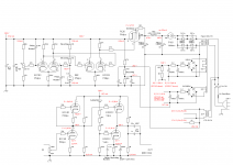
I'm looking for a very good (objective & subjective SQ) HV tube valve base regulator, looking for information I see at AudioXpress the attached schematic but I need to know:
-Max. Vin & Vout
-Min. Vin & Vout
-Max. & min. current
I guess is a very good tech design, also I have on hand the valves & sockets, suggested ideas to improve will be welcome.
TIA
Felipe

-Max. Vin & Vout
-Min. Vin & Vout
-Max. & min. current
I guess is a very good tech design, also I have on hand the valves & sockets, suggested ideas to improve will be welcome.
TIA
Felipe
Last edited:
Do you know Ohm's law? 😛
1N4764A is 100V zener, so the potentiometer slider always at about 100V, at minimum Vout and at maximum Vout.
At the first case slider is on the "upper" position, so 100V voltage on the 10k potmeter+22k resistor results
100V/32k=3.125mA current.
This current flowing trough 47k+10k+22k.
3.125mA*79k= about 247V as output.
At the second case 100V/22k= 4.545mA
4,545mA*79k= 359V
MAXIMUM current is about 80mA continuous if we account for about 20mA for the control loop, at a maximum of 280V input output differential.
I dont like the schematic, its correct and well thought out for what its worth, but a simple current source loaded EF184 will equal the performance, and can be run from the same winding.
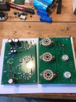
I have some boards for my own regulator design it uses three EL34. EF184 and 85A2
If you want, i can send you a board for the cost of postage. for you to try,
Ive tried uploading the schematic but wasnt able.
I dont like the schematic, its correct and well thought out for what its worth, but a simple current source loaded EF184 will equal the performance, and can be run from the same winding.
I have some boards for my own regulator design it uses three EL34. EF184 and 85A2
If you want, i can send you a board for the cost of postage. for you to try,
Ive tried uploading the schematic but wasnt able.
Attachments
Most of your questions are answered in the article itself (see Table 5 on page 6). There it's also explained that at Vout = 350 V the maximum Iout was 50 mA due to Vin not being high enough.
I've used this schematic (with some minor changes, like a 0B2 tube instead of the zenerdiode and a PL36 instead of the EL34) in my Aikido headphones amplifier.
I've used this schematic (with some minor changes, like a 0B2 tube instead of the zenerdiode and a PL36 instead of the EL34) in my Aikido headphones amplifier.
Attachments
MAXIMUM current is about 80mA continuous if we account for about 20mA for the control loop, at a maximum of 280V input output differential.
I dont like the schematic, its correct and well thought out for what its worth, but a simple current source loaded EF184 will equal the performance, and can be run from the same winding.
I have some boards for my own regulator design it uses three EL34. EF184 and 85A2
If you want, i can send you a board for the cost of postage. for you to try,
Ive tried uploading the schematic but wasnt able.
I'm interested in your regulator but I need the schematic & BOM, also what's the diff. Vin to Vout to work properly, max. & min. Vin Vout, etc.
I send you PM with my email for schematic & I will try to upload here.
TIA
Felipe
Thanks Andy, I know the information but I don't have the vacuum tubes on hand & I see the schematics a little bit complicated.
Do you know Ohm's law? 😛
1N4764A is 100V zener, so the potentiometer slider always at about 100V, at minimum Vout and at maximum Vout.
At the first case slider is on the "upper" position, so 100V voltage on the 10k potmeter+22k resistor results
100V/32k=3.125mA current.
This current flowing trough 47k+10k+22k.
3.125mA*79k= about 247V as output.
At the second case 100V/22k= 4.545mA
4,545mA*79k= 359V
Isn't mine design, it's an Audioxpress design.
- Home
- Amplifiers
- Tubes / Valves
- Valve/Tube HV regulator