I repeat, in filament bias each or the series connected diodes in fillament bias, passes the same current as the filament. About 1 amp in the 26 tube case and 0.25 amp in the 01a case.
And Felippe you should know this thing after so long here in the forum.
Here the first stage is biased to a couple mA I think. Correct me if I am wrong. So the diodes will see very little current for optimal operation, as Salas said.
If you have more questions about other circuits better ask at the appropriate thread.
George, it's the appropriate thread because I want to use in my Itch.
Please nota bene my name is Felipe not Felippe!!!
Salas don't said Sic can't be used, see Salas post 3249!!!
George with all respect I believe you are mixing filament with cathode bias, cathode bias can go with few mA as per 01A preamp.
Please nota bene my name is Felipe not Felippe!!!
Salas don't said Sic can't be used, see Salas post 3249!!!
George with all respect I believe you are mixing filament with cathode bias, cathode bias can go with few mA as per 01A preamp.
First, sorry for misspelling your name!
I only commented for the schematic you posted and you said that they are passing 83mA, which was not correct.
I am not mixing anything as I have built preamps with both topologies.
I also only said that the diodes were not optimum in this circuit , not that they can not be used.
Sorry to try to help you, won' t happen again.
Salas, if changing 15n in RIAA reduces or boosts HF then what effect changing 47n cap will produce?
I’m happy and proud 🙂
Thank yoy, Salas for the project!
Finally, after a long time I got the sound 🙂
Just now only a testing project in a coockie box, but will be finished, of course 🙂
Thank yoy, Salas for the project!
Finally, after a long time I got the sound 🙂
Just now only a testing project in a coockie box, but will be finished, of course 🙂
Attachments
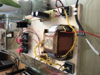
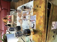
Sounds great. Just now testing with easy solution for 300v supply, no your design shunt.
The problems - have to fight with hum and seems high frequencies are too low. Have to check RIAA capacitors.
The problems - have to fight with hum and seems high frequencies are too low. Have to check RIAA capacitors.
Use shielded signal cable if you didn't. Show us inside the cookie box if not solving hum, maybe we see something to suggest changing. About HF the lower the last parallel cap's value the higher the HF (C3 in rev1.2), but it could be missing treble due to a mistake as well.
Thanks, Salas.
Problem solved. Gone through earlier posts and find some grounding problems in my design + ground loop. Also one error at input and no more hum or buzz at all.
Next have to find proper caps for RIAA (now cheap trash) and may be experiments for interstage cap. Just now russian ССГ-2.
Problem solved. Gone through earlier posts and find some grounding problems in my design + ground loop. Also one error at input and no more hum or buzz at all.
Next have to find proper caps for RIAA (now cheap trash) and may be experiments for interstage cap. Just now russian ССГ-2.
Thanks, Salas.
Problem solved. Gone through earlier posts and find some grounding problems in my design + ground loop. Also one error at input and no more hum or buzz at all.
Next have to find proper caps for RIAA (now cheap trash) and may be experiments for interstage cap. Just now russian ССГ-2.
That's all very good. Congratulations. Let us know with what value Riaa HF cap you ended up with. Must be tight in tolerance spec for good left-right response balance if you can't otherwise screen some looser spec samples with a good LCR meter. But while deciding its optimum value in your system, recheck that the VTA geometry and needle ware are not possibly neglected factors for dulling the HF.
Finished with PIO caps K40Y-9 47nF and 15.5nF. Tried also for interstage K40Y-9, but old silver ссг-2 sounds much better for me.
Salas, how important are caps c1 and c5. Have to try different ones for better sounding?
Salas, how important are caps c1 and c5. Have to try different ones for better sounding?
Hello,
sorry for asking, but what is
Greetings
Ulf
sorry for asking, but what is
... old silver ссг-2 ...
Greetings
Ulf
Mildly important, but they worth a try while you are on it.
sure, will try
Hello,
sorry for asking, but what is
Greetings
Ulf
Old soviet mica capacitor with silver plates. 0.1 uF +- 0.3%
http://radiomir.org/shop/radiojelek...sljudjanoj-s-serebrjanymi-obkladkami.html?i=1
Lately I've been on the hunt for a new tube phono to build. The fact that this one uses the 6N2P-EV (which I have in abundance) and a relatively small number of other parts has made it a really attractive option.
I've previously built a couple of tube phonos off PCB and about four different HV B+ power supplies (including a SSHV2 and a Janus Shunt). I know this isn't a beginner project, but I'm still tempted..
I've noticed in this thread some chatter over the years about a potential PCB. Since I have been wanting to build a new tube phono AND try designing a PCB, here I am. I thought I'd at least get a preliminary design out here to see if anyone thought this might be workable.
In the attached, I started with a hand sketched point-to-point wiring diagram and tried to to arrange the parts in a somewhat logical way to simplify the PCB. This version includes:
.75mm GND track
.50mm Heater Tracks
.50 B+ Track (with .50mm minimum clearance)
35mm LS capacitor pads to fit NOS Russian caps or a wide range of various boutique caps
.1uf caps are footprinted for Kemet 1% (F461BC104F400A)
All resistors except R2 and R10 are Vishay CMF55. R2 and R10 are Vishay CPF2.
If this looks like a viable start, I'd be interested in getting input (even if it never goes to fab). If it's a complete no-go because of part layout/wiring complexity/etc, that would be helpful to know too so I can just cut bait and buy a Broskie PH-2 kit!
Thanks
Attachments
- Home
- Source & Line
- Analogue Source
- Valve Itch phono