I use the second one, because the signal is directly connected to the next grid,
instead of going through a coupling capacitor.
instead of going through a coupling capacitor.
Thanks rayma. I was thinking along those lines, but wonder if the capacitor grounding the grid for ac, has any negative effects?
Thanks rayma. I was thinking along those lines, but wonder if the capacitor grounding
the grid for ac, has any negative effects?
The second stage cathode being at an elevated potential could cause some extra hum,
but the filament could also be elevated. The RC filter to the lower grid needs to be effective
at removing the signal. The first plate DC voltage does affect the operating point of the
second stage.
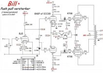
Both are poor choices unless there's a very compelling reason to *not* have normal drive to both output valves.
All good fortune,
Chris
All good fortune,
Chris
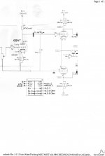
Mona. Thank you for that. I hadn't seen that version of the schematic. My concern is that the constant current tail will have 130volts across it and the transistors aren't rated for that voltage. Also will the ECC99 heaters need elevating? Cheers. Matt
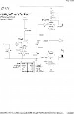
The capacitor grounding the grid has almost the same effect as a coupling capacitor, but most people do not realise this. A good LTP phase splitter will have high differential-mode gain and low common-mode gain. The LTP input signal appears between the anode of the previous stage and ground. To pick up this signal one LTP grid has to be coupled to the anode, and one has to be coupled to ground. At least one of these connections has to include a capacitor to block DC. It doesn't matter too much which grid you choose to have the capacitor.Matt Rowland said:I was thinking along those lines, but wonder if the capacitor grounding the grid for ac, has any negative effects?
It's a ~11mA CCS with 10k in series, you loose 110volts there, no problem.Mona. Thank you for that. I hadn't seen that version of the schematic. My concern is that the constant current tail will have 130volts across it and the transistors aren't rated for that voltage. Also will the ECC99 heaters need elevating? Cheers. Matt
The +15V supply can have an other value, 6...24V is ok.
And yes elevate the heater to 50V, enough for the 6N6/ECC99 and not to much for other tubes.
Mona
The capacitor grounding the grid has almost the same effect as a coupling capacitor, but most people do not realise this. A good LTP phase splitter will have high differential-mode gain and low common-mode gain. The LTP input signal appears between the anode of the previous stage and ground. To pick up this signal one LTP grid has to be coupled to the anode, and one has to be coupled to ground. At least one of these connections has to include a capacitor to block DC. It doesn't matter too much which grid you choose to have the capacitor.
Not the same effect. It works like an all pass filter, shifting phase between phase-splitting outputs, introducing common-mode output on lower frequencies. I did that in my Pyramid amp design, and had to take care of infra-sound frequency instability.
Both are poor choices unless there's a very compelling reason to *not* have
normal drive to both output valves.
Of course push-pull drive to a diff amp is ideal, but these circuits both lack that.
Many tube amplifiers have had similar circuitry, including the Marantz Model 8B and 9,
so good performance is possible with such a topology.
Last edited:
High Wavebourn. So how did you cure the instability at LF?
As usual, playing with values of RC, this time in common mode servo feedback.
Attachments
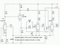
As I said, "almost the same effect". Not an all-pass filter, but a lead-lag filter. As you say, it can affect common-mode output at very low frequencies so may help or hinder subsonic loop stability. Within the normal audio frequency range it has a very similar effect to a coupling cap.Wavebourn said:Not the same effect. It works like an all pass filter, shifting phase between phase-splitting outputs, introducing common-mode output on lower frequencies.
I don't see any compensation for this subsonic instability in amps like the Dynaco 60watt for example. How does it manifest, saturation of the o/p transformer core?
Whether there is subsonic instability depends on many things. As I said, this lead-lag filter may help or hinder stability. The ratio of differential-mode gain to common-mode gain in the LTP is an important factor, as is the exact response of the output stage to common-mode grid drive. The lead-lag filter does not in itself create instability as it is just one circuit feature among many others.
The criterion of instability is, amplification factor greater than 1 on the frequency where phase shift is 180 degrees. Change values of coupling RC pairs, and you are safe.
- Home
- Amplifiers
- Tubes / Valves
- valve input stage and driver/phase inverter coupling