Hi
Bit of help please. I have just built a valve buffer stage to replace the IC one in my preamp. The phone stage is valve using two nos. Mullard ECC83’s and was a revelation when it replaced the IC one. So no problem there. The power amp is a WAD K5881 which I built years ago and has upgraded components and is great.
The small problem I have is that the new buffer stage (see circuit below) sounds fantastic but has a slight hardness at the top end, apart from this everything else, sound wise is great. Questions are. Do valves get sweeter after a while, fitted are Tesla E88CC’s and were only £8 each so a bit cheap. Also the input cap is a cheap wima polycarbonate, whereas the output cap is a very good Polypropylene film. Could these be the problem?
Thanks for help, Duke1978
Attachments
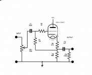
I also suggest to remove grid stopper, a cathode follower doesn't need it, and take C2 directly from the cathode.
This schematic developed for E88CC.
12AX7/ECC83 and 6922/E88CC are totally different tubes.
For example with ECC83 the output impedance of CF about 520R, with E88CC 94R.
At line level input the distortion is low with both tubes, but E88CC produce about 1/10 distortion than ECC83 (in this project).
12AX7/ECC83 and 6922/E88CC are totally different tubes.
For example with ECC83 the output impedance of CF about 520R, with E88CC 94R.
At line level input the distortion is low with both tubes, but E88CC produce about 1/10 distortion than ECC83 (in this project).
Leave C2 where it is. A resistor at the output of a follower helps keep it stable into capacitive loads. R2 has this function, as well as provdiding bias for the valve.
Be aware that a true buffer has no sound at all, but it may avoid the unwanted sound of other things such as cable capacitance on those rare occasions when this is a problem.
Be aware that a true buffer has no sound at all, but it may avoid the unwanted sound of other things such as cable capacitance on those rare occasions when this is a problem.
The small problem I have is that the new buffer stage (see circuit below) sounds fantastic but has a slight hardness at the top end, apart from this everything else, sound wise is great. Questions are. Do valves get sweeter after a while...
No
...fitted are Tesla E88CC’s and were only £8 each so a bit cheap. Also the input cap is a cheap wima polycarbonate, whereas the output cap is a very good Polypropylene film. Could these be the problem?
Thanks for help, Duke1978
Ran some loadlines and the design looks solid. The 470R bias resistor can stay.
Have you o'scoped the output as working into the input/output cables? The E88CC is an RF type originally intended for use as a VHF cascode. This high frequency hardness could be due to an instability that's leading to a damped RF oscillation that's quite possible as the type likes making RF. You might try increasing the grid stopper to something like 4K7. Make sure it's a C-comp type as these have lower internal inductance than metal film types.
Do not remove the grid stopper R9, 6DJ8 based cathode followers can oscillate without it. (from experience!)
Do not remove the grid stopper R9, 6DJ8 based cathode followers can oscillate without it.
AGREED! Also, use a carbon composition part in the grid stopper role. Additional protection against parasitic oscillation can be obtained by using a 100 Ω carbon film stopper on the plate.
Replacing C1 with a low WVDC polystyrene part may help.
The value of C2 is suspect. If the buffer is to work into the 10 Kohm IHF "standard" load, the minimum value necessary is 3.3 μF.
Be aware that a true buffer has no sound at all, but it may avoid the unwanted sound of other things such as cable capacitance on those rare occasions when this is a problem.
Anything that misbehaves has a sound. The difference in sound is, how it misbehaves. Bob Cordell on BAF articulated it very well. ;-)
A true buffer does not misbehave, therefore it has no sound. It may remove the sound of something else misbehaving.
Many real buffers can misbehave, and not everything called a buffer is really a buffer.
Grid stoppers do not have to be CC, as the aim is simply to add sufficient loss. Grid stoppers can be inductive resistors, or resistive inductors.
Many real buffers can misbehave, and not everything called a buffer is really a buffer.
Grid stoppers do not have to be CC, as the aim is simply to add sufficient loss. Grid stoppers can be inductive resistors, or resistive inductors.
A true buffer does not misbehave, therefore it has no sound. It may remove the sound of something else misbehaving (...) and not everything called a buffer is really a buffer
Is this the root of the 'No True Buffer' fallacy?
Do not remove the grid stopper R9, 6DJ8 based cathode followers can oscillate without it. (from experience!)
Many times if the circuit oscillates, is not because of the tube, instead by an improper wiring. The circuit below is a Colpitts oscillator. If the input wiring isa bit inductive, and the capacitances are the wiring and input/output ones clearly form a Colpitts oscillator.
Adding a grid stopper only reduces the Q of the tank, but oscillations can still be present. It is a good idea to reduce the strays, IMHO.
Attachments
Thanks to you all for the help. I will try some of your suggestions.
After using solid state amps for 40 years, I couldn’t believe how much better valves are.
After using solid state amps for 40 years, I couldn’t believe how much better valves are.
As in the vast majority of the things of the life: 50% will be sure that tubes are better, and 50% is sure that transistors are better. Each one sees the same thing in a different way.
Try yourself and tell us your opinion.
In the other hand, only one tube stage is few probable to change the sound in an appreciable way or amount.
Try yourself and tell us your opinion.
In the other hand, only one tube stage is few probable to change the sound in an appreciable way or amount.
Duke1978, have you tried to replace the buffer for a wire?
Maybe you do not need the buffer at all.
Maybe you do not need the buffer at all.
Last edited:
Thanks to you all for the help. I will try some of your suggestions.
After using solid state amps for 40 years, I couldn’t believe how much better valves are.
Neither do us.
Unity gain buffers are the most transparent (i.e. "changes nothing") configurations you can build, so I´d be very surprised you could measure, (let alone hear) any deviation within the audio band.
Besides, maybe, less than 1dB signal loss.
Leaving "confirmation bias" aside, of course.
- Status
- Not open for further replies.
- Home
- Amplifiers
- Tubes / Valves
- Valve buffer stage