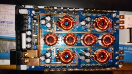
Hello, got this amp for repair. Somebody tryed allready and some parts missing.
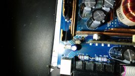
Can anybody tell me the Value of the missing capacitor(C33) and the burned resistor in the Picture? Its from the power supply, in the corner to the speaker terminals.
Maybe below the missing cap is something more missing, but iam not sure. I think its a coupling capacitor, because one end is going to the wire which is connected to the Amp body (Heatsink)
Attachments
If no one else has a definitive answer, 0.1uF. The following is for the K2.02.
STEG K2.02 118042150 RE0.0-E3 CAR AUDIO AMPL SM Service Manual download, schematics, eeprom, repair info for electronics experts
STEG K2.02 118042150 RE0.0-E3 CAR AUDIO AMPL SM Service Manual download, schematics, eeprom, repair info for electronics experts
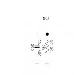
These shunt high frequency noise and any DC leakage to ground. Many amps use 0.1uF and 1k. The value for these isn't generally critical.
So small problem i think. If i apply only power, no remote the Resistor starts smoking.
Without the ground wire ( connected from the resistor and cap to heatsink) the amp works ok. What could be the problem?
I think there must be somewhere a diode short. Because if i measure with diode check from plus to the ground cable it shows 033, from minus to the cable the same.
Without the ground wire ( connected from the resistor and cap to heatsink) the amp works ok. What could be the problem?
I think there must be somewhere a diode short. Because if i measure with diode check from plus to the ground cable it shows 033, from minus to the cable the same.
Last edited:
You may have a bad insulator. Touch the scope probe to the heatsink to see what sort of voltage is on it.
i removed the clamps and removed the board. It seems that a cap is charging, and stops at 440. Plus from the tester at the ground cable, minus at the B+ Terminal. Between the cable and B- 033 because of the resistor.
Another question, i think the amp has not enough output. The previos technician changed one op amp (IC3 TL072) and installed a 5532 from JRC in the preamp section.. Can this be a problem with less input?
Last edited:
Iam not so familiar with op amp paramters, but i expect, that Avd (Large Signal differential voltage amplification) is the right parameter. TL072 has typical 200V/mV and the NE5532 has 100V/mV. That means, half of output, or i have to double the input gain to reach the same output as with a TL072. Can somebody tell me are iam correct???
I have checked, how much voltage i have to inject. Its definitely to low output.
If i inject 100Hz with 7V, and the Gain is at 5V (minimum), i get at the Output only 5V. If i turn the gain to maximum 0,2V, then i have 50V without clipping. Tested without load, only oscilloscope at the output. Inputvoltage is 12,5V. So, whats wrong? Should i change the OP AMP?
If i inject 100Hz with 7V, and the Gain is at 5V (minimum), i get at the Output only 5V. If i turn the gain to maximum 0,2V, then i have 50V without clipping. Tested without load, only oscilloscope at the output. Inputvoltage is 12,5V. So, whats wrong? Should i change the OP AMP?
In general, the gain of an op-amp is determined by the resistance in the input and feedback circuit. Typically, I wouldn't expect to see more than a gain of about 20 in any stage and typically much less in most instances.
Does the preamp section in the amp you have match the preamp section in the diagram for the amp link posted?
Does the preamp section in the amp you have match the preamp section in the diagram for the amp link posted?
Yes, its the same preamp. I use the amp without any crossover cards ore settings. Just stereo straight in and out.
Found two burned smd resistors. One is going on Pin 6 of IC1. Not sure wich resistance, because no more marking and nothing on the board.
IC has been changed with a NE 5532. On IC1 Resistor to Pin 2 and Pin 5 are burned.
IC 1 Pin 5 and 7?
IC 1 Pin 5 and 7?
So, at max gain i have on each pin the same level as i injecting.
Oscilloscope shows at 5V/div approx 4V to positive and to Negative
Oscilloscope shows at 5V/div approx 4V to positive and to Negative
Sorry, the burned resistor are Pin 2 and Pin 6. The other end of the resistor ends between to resistors. So i think its a Voltage divider.
I think R51 and R29
I think R51 and R29
Last edited:
R51 and 29 are essentially part of a divider. They pull down the signal in the feedback loop and increase the gain of the circuit. Without them, the input and output of the op-amp is likely to be the same. Replacing those resistors should increase the gain of that op-amp stage to about 10x.
- Status
- Not open for further replies.
- Home
- General Interest
- Car Audio
- Value of Cap for Steg K2.04