Many of the "dreaded" series types are strange voltages. Such as a great power tube which needs 25V, 35V, or 50V(!) to heat properly.I’m not sure I understand this correctly.
The "dreaded" 12A_7 types can also be run in series strings but since they can eat common 6.3V or 12.6V nobody is frightened. In fact the common series-string radio had three 12V types: 12BE6, 12BA6, and 12AV6.
Fair enough! You are basically saying follow the specs with “series heaters” versions (and all other heaters). I mistakenly thought there was more.The “series heater” versions don’t have to be run in series. They just require 300, 450 or 600 mA of heater current at whatever voltage it ends up being - not necessarily 6.3 or 12.6 volts. 10CW5 requires 10.6 volts - it can’t just run off a 6.3 V heater winding. <snip>
There is one more consideration: some tubes are specifically rated with "controlled heater warmup characteristic" for use in series strings, otherwise you might have a heater in the chain over-voltaged during startup. See description in this datasheet.
https://frank.pocnet.net/sheets/093/6/6SN7GTB.pdf
https://frank.pocnet.net/sheets/093/6/6SN7GTB.pdf
That can be a problem when running a series string off of 120 volts AC, like many vintage radios and most TVs did. The string might contain 4 volt and 36 volt tubes and everything in between. They would need to come up to temp at about the same rate or the 4 or 6 volt tube in the tuner might see a bit too much for a bit too long. It was common to run a pair of 50C5 and a single 12AX7 in series in a console stereo record player. Needs the “A” version or you could be rolling the dice. The preamp tube was cheap back then, but still…. if you got an h-k short from repeated overstress it will cost you more than just a couple bucks for a tube if you ended up in cardiac arrest.
If you were running two 12A*7 and a resistor in series so that you could use 26 volt tubes in your power stage and use the same heater transformer, you should stick with the controlled warm up type. But with only 26 volts available instead of 120 the overvoltage conditions you could get during warm up aren’t THAT serious if you didn’t.
If you were running two 12A*7 and a resistor in series so that you could use 26 volt tubes in your power stage and use the same heater transformer, you should stick with the controlled warm up type. But with only 26 volts available instead of 120 the overvoltage conditions you could get during warm up aren’t THAT serious if you didn’t.
I was testing out a Dyna PAS preamp once, and pulled some random 12AX7s out of my stash. This preamp runs pairs of 12.6 heaters in series (at a slightly lower voltage.) I think I had a Sovtek and a Sylvania in series, they ended up with at least 10% differing voltage across them.
Don't completely discount "weird" tubes. They're used in some vintage test equipment and one could probably make a list of desirable types. They won't get the $$ of the highly desired audio tubes, but if I need an oddball tube to keep equipment going, I'll pay whatever I have to.
Just a weird heater voltage.. make a forward converter that you drive off some low voltage rail and throw on a winding for every oddball voltage you need, all floating.
People act like switching power supplies are always full of noise, but they're pretty easy to make clean if you know a few key ways the noise is produced.
People act like switching power supplies are always full of noise, but they're pretty easy to make clean if you know a few key ways the noise is produced.
Just a weird heater voltage.. make a forward converter that you drive off some low voltage rail and throw on a winding for every oddball voltage you need, all floating.
People act like switching power supplies are always full of noise, but they're pretty easy to make clean if you know a few key ways the noise is produced
Thanks for all the informative responses.
Looks like there's some possibilities here.
I only have the tubes listed in singles
Unless there's a bracket with a number in it, indicating quantity. I only have a few with 2. With the exception of
6AQ5's there's quite a few.
A bit more information.
I'm on vacation and these tubes have been offered. So I'd have to bring them back.
I have built a few vacuum tube devices but I'm still an very much a novice. So i would be more interested in designs that have been proven, because I don't have enough experience to experiment.
Just as easy to throw a winding on a 60 Hz power toroid. Use bell wire and not even have to worry about tape.Just a weird heater voltage.. make a forward converter that you drive off some low voltage rail and throw on a winding for every oddball voltage you need, all floating.
People act like switching power supplies are always full of noise, but they're pretty easy to make clean if you know a few key ways the noise is produced.
The problem with DC-DC converters is you get what you pay for on E-bay. Making your own is the way to go, but beyond the capabilities of typical tube-o-philes.
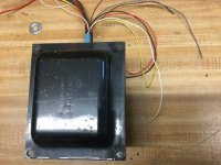
If you are into making your own transformers, you could end up with something that looks like this. Think there are enough wires there?
Attachments
Most people assume switching supplies are real difficult (and maybe they just seem easier to me because I have a lot of experience designing them), but there are certain ones that are pretty straightforward to understand.
If you can understand how current ramps up and down in an inductor vs the voltage in each state (transistor on and off), and how energy is getting in and out of the core, something like a forward or flyback converter can be "easy".
They can also be just about as fun to breadboard and experiment with as tubes 🙂
Forward converters are quite easy for devices with constant DC loads - like tube heaters. The actual amplifier, however can run into discontinuous operation of the inductor. Then it gets more complicated. Or just build a half bridge, and run it at 95% duty cycle unregulated and not worry about continuous operation of the output filter inductor. It will be about as good as a core-coil 60 Hz supply as far as regulation. ZVS/ZCS don’t necessarily need to be employed at reasonable power levels - a necessity at 2kW but not to run a couple of tube heaters (or small-ish amp).
How noisy a supply is usually depends on your layout skill/capability more than anything. What comes out of China is often rolling the dice. Might be clean enough. May be as bad as a fluorescent lamp ballast.
How noisy a supply is usually depends on your layout skill/capability more than anything. What comes out of China is often rolling the dice. Might be clean enough. May be as bad as a fluorescent lamp ballast.
I wonder if you're thinking of flyback converters? Those will need a feedback loop for regulation, as they're delivering packets of energy to the output, and need to know how much / how often.
A forward converter outputs pulses of voltage that are just the input * the turns ratio - easy peasy 🙂
You wouldn't use one in CCM, so no questions about what changes at the boundary. If you're putting in more energy than your load and reset winding can get out, you're headed straight for saturation (where the core turns into a short and your transistor turns into charcoal).
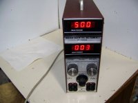
The cheap and easy B+ solution. Hoefer PS500XT electrophoresis supply.
0 to 500V, 0 to 400 mA, regulated, metered. Make sure to get a later one with a fan in back. Needs a small ferrite inductor and capacitor added to filter the output better.

0 to 500V, 0 to 400 mA, regulated, metered. Make sure to get a later one with a fan in back. Needs a small ferrite inductor and capacitor added to filter the output better.
Attachments
Last edited:
6AW8 is a triode/pentode tube that I've seen used as a voltage amp/concertina phase inverter combo. Can be microphonic though.
6AV6 is half of a 12AX7 (plus a couple of diodes that you can ignore) in a 7-pin mini bottle.
6AQ5 is a 6V6 in a 7-pin mini bottle.
6AV6 is half of a 12AX7 (plus a couple of diodes that you can ignore) in a 7-pin mini bottle.
6AQ5 is a 6V6 in a 7-pin mini bottle.
The cheap and easy B+ solution. Hoefer PS500XT electrophoresis supply.
0 to 500V, 0 to 400 mA, regulated, metered. Make sure to get a later one with a fan in back. Needs a small ferrite inductor and capacitor added to filter the output better.
Yes these are cheap and cheerful, I blew one out then picked up another. My mistake... Its important when breadboarding with one of these that you breadboard the circuit entirely floating off the house ground. These electrophoresis supplies do not like either neg/pos output tied to ground at all. I found that out the hard way with a $49 unit I picked up, it quietly/undramatically blew out its protection circuit. After that happened the voltage pots would no longer bring up voltage slowly from zero, you would have to crank the pot up to 400V then you could go backwards into the voltage you wanted (not the way you want this to work). These are used to separate DNA molecules I guess in a gel tank, for that process to work those tanks obviously cannot be grounded you just want to move the molecules between two points.
Hmmm. Was that meltdown with a Hoefer PS500XT? I wasn't aware this model had ANY protective circuits. Some of the electrophoresis supplies out there require a minimum load on them to come up too, but not the Hoefer PS500. I could see where protected models could have a ground current fault monitor, but they -should- just shut down.
I just measured my PS500XT with an Ohm-meter and it shows open circuit between either output terminal and chassis ground.
Then I tried a clip lead between the + terminal and chassis and it shuts down at 500V (not sooner) with the meters alternately flashing. It recovers when I re- power-up though. I wasn't aware of that feature. It must be sensing AC current thru a small cap. It uses a TL594CN controller chip, and a LM358N Op Amp chip. Probably the Op Amp chip is monitoring Gnd current somehow. For the meters to be alternately flashing on and off, there must be some feature in the TL594CN chip. Should be documented in the datasheet.
Last edited:
My PS500XT unit has sockets for the ICs. (sockets even for the power switching transistors) If the LM358N Op Amp went, it should be easy to fix. I would replace that flaky pot though first.
If the amplifier being tested had HF going thru it, it might trigger the Gnd current fault sense (since it seems to be AC coupled), and maybe could put too much current thru a cap sensor to the Op Amp. (the Ground Fault sensor design may be sensing common mode HF switching noise, to enable a cap coupled sense)
Probably can disable the Ground current sense by removing some small cap going to the Op Amp circuitry. Although some would consider that a good safety feature to have for testing or repair work
. A Medical isolation xfm,r for isolated power to the equipment being tested, would likely disable the Ground Fault sensing. ( I use some Magnetek N-90MD 250 VA isolation xfmrs for testing, 127 pF common mode from primary to secondary ) But with a HF sense in the Hoefer, it -might- not disable that due to higher common mode capacitance in an ordinary isolation xfmr. ( My Magnetec N-66A 250 VA ordinary isolation xfmr has 310 pF common mode, still pretty good )
Last edited:
Mine was a Fisher where I let it touch safety ground and it blew. I got a second Fisher for breadboarding but now I just don't bring the house ground into play at all on the breadboard.
- Home
- Amplifiers
- Tubes / Valves
- Vacuum tubes worth keeping?