If severeal tubes blow with very different capacitances then I agree, the data spread won't tell us a great deal. But maybe we'll get lucky and they'll all blow with very similar capacitances, in which case we can make some useful deductions. Yes it would be better to test a hundred tubes, or a million tubes, but we don't have them, so handwringing over unknowns and 'maybes' is just an excuse not to try anything. You have to start somewhere. I don't see any vagueness here, with known voltages, resistances, and capacitance.
I have used damper tubes in my last three amplifier builds. These are stereo amps in the 15 to 40 watt range per channel.
I use two damper tubes to replace a single 5AR4 or 5U4 rectifier tube.
I have used the 6D14P, 6C10P and 6C19P and found they all work well and are low cost.
Below is a chart I made of the measured voltage drop at about 420mA plate current per plate.
I used 420mA as a representative average power supply peak rectifier current.
Tube Va Ia
5U4GB 67V 425mA
5C4 48.3V 423mA
5AR4 23V 416mA
6C19D 32.5V 435mA
6D14C 29.2V 438mA
6C10P 35.7V 420mA
The chart shows the 5AR4 has the lowest loss at 23V.
Next in line at 29.2V loss is the 6D14C damper tube. This is only about 6 volts more loss that the 5AR4.
The 6C19D at 32.5V loss is a a close third.
I find a pair of the above make a good replacement for a 5AR4 tube.
The small extra voltage drop over a 5AR4 can be made up in the transformer if needed or in most cases is simply close enough.
The 6C10P with 35.7 volts loss makes a good 5U4 replacement with a small added resistor to add back some the large loss that a 5U4 has.
In terms of ruggedness I find these tubes stand up to short term over loads better than current production 5AR4s I had purchased.
My investigation of damper tubes came out of frustration I experienced when replacing aging NOS 5AR4 with current production tubes only to see the new current production tube fail in months of use.
So far in my experience damper tubes are more rugged and forgiving than current production 5AR4s.
I do watch the size of the first capacitor and keep it at 50uF or less so the peak current is reasonable.
One bonus of the damper tubes for me is they have a very slow warm up time of about 30 seconds. This means by the time the B+ is ramping up the other tubes are nearly fully warmed up. The result is little to no voltage over shoot in the power supply at start up giving your power supply capacitor a easier time.
I personally like the look of top cap tubes as well.
The largest issue for me is finding a isolated extra 2 amps of current at 6.3 volts for the damper tubes filaments. There is no free lunch.
If there is a long term reliability issue with these tube in rectifier service I have not experienced it yet.
In testing these on my uTracer they can produce high peak currents for the short time of the test pulse.
See the chart below for a 6C19D. It can pass 957mA at less that 60 volts drop.
This is a high peak current and no way it can be continuous but does support the data sheet claim of 450mA peak current may be conservative.
Ia(mA) Va
31.37mA 2.77V
54.41mA 5.71V
72.74mA 6.57V
106.06mA 10.46V
137.58mA 13.3V
173.36mA 15.02V
224.71mA 19.77V
271.26mA 22.44V
317.55mA 25.11V
369.63mA 27.71V
423.68mA 31.36V
466.28mA 33 V
517.77mA 38.82V
564.38mA 39.34V
612.44mA 41.99V
663.8mA 44.6V
715.68mA 48.28V
773.09mA 50.81V
826.29mA 53.4V
890.16mA 55.87V
957.31mA 59.36V
Last edited:
Sorrento, your sim indicates the effective DCR is 1 ohm reflected over to the secondary, and similarly the secondary voltage is 330Vpk reflected over to the secondary (ie. 300Vrms) ? Did you cross-check that with PSUD2 ?
Given the threads expected demise mechanism is arcing, then the use of a bridge rectifier and only circa 300Vac suggests arcing would have to occur at a significantly lower PIV than what many may expect would be applied in an application. I'd also expect that for an arcing form of demise, and given that results from outgassing or breakdown of cathode surface, then such a demise process should be identifiable prior to arcing via measurement of diode insulation resistance at say 1kVdc using a common megger type meter.
Like a common valve rectifier, if the demise is slow then the use of an ss diode in series with the anode would achieve the same extension of service life for a damper diode.
I used a silicon voltage tripler and cap multiplier to get 125v B+ for 2x 6922 preamp.
110db. S/N dead silent.
Use 2000 piv diodes and be done with problems.
110db. S/N dead silent.
Use 2000 piv diodes and be done with problems.
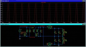
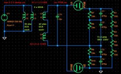
The voltage source represents 230V mains, 1 ohm is just an arbitrary number for its low impedance.Sorrento, your sim indicates the effective DCR is 1 ohm reflected over to the secondary, and similarly the secondary voltage is 330Vpk reflected over to the secondary (ie. 300Vrms) ? Did you cross-check that with PSUD2 ?
The transformer model includes a primary DCR of 30 ohms and a secondary DCR of 42 ohms for each of the two parallel 65VA transformers. DCR not shown in the drawing but part of the inductor model.
The sim results match the voltages and currents in my actual test setup.
Sorrento, do you have your test setup running full-time? Was the intention to leave it running until you get a PY88 failure?
I get the same waveform with PSUD2 using a bridge of PY88 and a slightly higher secondary voltage.
I get the same waveform with PSUD2 using a bridge of PY88 and a slightly higher secondary voltage.
My primary intention was to show that immediate fireworks don't happen with Booster Diodes just because of higher load capacitance.
Some predicted that to happen, but it could afford more than that ...
In the meantime I have upgraded my test setup to a 2 tube Delon doubler using the same transformers.
Which means twice the reverse voltage stress and at the same time twice the peak current.
A spoiler information beforehand: Still no fireworks and no signs of discomfort from the valves ...
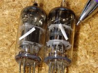
Here's the new setup and results:
A pair of EY88 in a Delon doubler circuit.
They seem to be rebranded russian 6D20P (no European manufacturer had nickel plated pins)
2 isolation transformers 65VA 230 / 230V in parallel, 130VA total.
Combined primary DCR 15 Ohm.
Combined secondary DCR 22 Ohm.
AC secondary no load 265V RMS.
Straight into 2 x 1000uF in series..
No series resistors aside from transformer DCR.
Various incandescent light bulbs as load.
No preconditoning, no power sequencing, just switch on, heaters and hv together.
Watching lamps coming to life gradually, and stay on.
No problem whatsoever ... no fireworks, no red plating ...
DC output w/o load 675V.
DC load current with 4x25W/230V in series 86mA and 575V.
DC load current with 4x40W/230V in series 138mA and 552V.
DC load current with 4x60W/230V in series 196mA and 510V.
The attached sim again matches the measurements well enough and tells us this:
25W lamps: peak current 600mA, plate dissipation 2.5W
40W lamps: peak current just short of 800mA, plate dissipation 4.6W
60W lamps: peak current just short of 1A, plate dissipation 7.5W
(note: DS m,ax is ü.5A peak and 5W dissipation).
No more excuses, they are tough.
Survived 600V reverse, 200mA DC, 1A peak currents into 1000uF, all at the same time.
For how long, we don't know yet ... maybe the OP is going to volunteer ... ?
Some predicted that to happen, but it could afford more than that ...
In the meantime I have upgraded my test setup to a 2 tube Delon doubler using the same transformers.
Which means twice the reverse voltage stress and at the same time twice the peak current.
A spoiler information beforehand: Still no fireworks and no signs of discomfort from the valves ...
Here's the new setup and results:
A pair of EY88 in a Delon doubler circuit.
They seem to be rebranded russian 6D20P (no European manufacturer had nickel plated pins)
2 isolation transformers 65VA 230 / 230V in parallel, 130VA total.
Combined primary DCR 15 Ohm.
Combined secondary DCR 22 Ohm.
AC secondary no load 265V RMS.
Straight into 2 x 1000uF in series..
No series resistors aside from transformer DCR.
Various incandescent light bulbs as load.
No preconditoning, no power sequencing, just switch on, heaters and hv together.
Watching lamps coming to life gradually, and stay on.
No problem whatsoever ... no fireworks, no red plating ...
DC output w/o load 675V.
DC load current with 4x25W/230V in series 86mA and 575V.
DC load current with 4x40W/230V in series 138mA and 552V.
DC load current with 4x60W/230V in series 196mA and 510V.
The attached sim again matches the measurements well enough and tells us this:
25W lamps: peak current 600mA, plate dissipation 2.5W
40W lamps: peak current just short of 800mA, plate dissipation 4.6W
60W lamps: peak current just short of 1A, plate dissipation 7.5W
(note: DS m,ax is ü.5A peak and 5W dissipation).
No more excuses, they are tough.
Survived 600V reverse, 200mA DC, 1A peak currents into 1000uF, all at the same time.
For how long, we don't know yet ... maybe the OP is going to volunteer ... ?
Attachments

Many years ago I was given lots of boxes like this full of loose tubes in various condition. It took nearly 5 years of weekends to sort them all and toss the obvious trash. In the process you find some amusing things like a pair of 6AG5's that included a spare heater inside the glass. Unfortunately, installation instructions were not furnished."I see dead rectifiers."
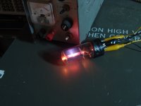
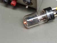
I also found a 6AX4GT damper diode with a hole in the plate probably from a long term overload condition. The picture didn't turn out good due to glare on the glass, so I hooked the heater up to a power supply and turned off the room lights to make the hole more obvious. I was about to toss it in the trash when I got the brilliant idea to test it. Would it still pass current?
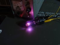
Two more clip leads and another power supply provided the answer. The data sheet shows 32 volts of drop at 250 mA. It also states "Operation of this tube as a power rectifier is not recommended." I cranked up the power supply until 250 mA flowed. There was about 25 volts across the tube. This thing was still in spec. Well, I'm not going to put it into anything that I am going to build, so there is only one thing left to do. Turn up the heat!
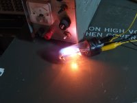
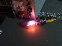
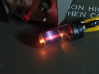
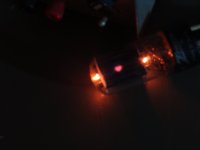
Ever heard of cathode rays? They turn into ion beams at about 1 amp of current and get brighter with time as the tube becomes gassier. OK, this is getting boring. Turn it up. 2 Amps turn the plate white hot and make for a mean looking beam. Lets just dime the power supply. Both the voltage and current knobs are cranked. The current is in limit at a little over 3 amps and the voltage is slowly decreasing and the glow gets brighter. Eventually another hole opens on the other side. Note the projected image of the RCA octagon on the power supply under the tube. This led to a plasma ball enclosing the top half of the internal structure, followed by arcing and bits of metal flying inside the tube which hit the glass hard enough to crack it and kill the fun.
Attachments
-
 DSC00092.JPG292.1 KB · Views: 57
 -
 DSC00091.JPG393.9 KB · Views: 58
 -
 DSC00089.JPG381.7 KB · Views: 61
 -
 DSC00086.JPG362.3 KB · Views: 60
 -
 DSC00085.JPG359.9 KB · Views: 59
 -
 DSC00080.JPG349.2 KB · Views: 61
 -
 DSC00074.JPG336.7 KB · Views: 59
 -
 DSC00068.JPG129.4 KB · Views: 63
 -
 DSC00067.JPG208.2 KB · Views: 62
 -
 two_of_them.jpg104.7 KB · Views: 65
 -
 Box_o_tubes.jpg116.1 KB · Views: 62

One last experiment for today. I found a couple of 100W / 230V light bulbs.
Same setup with EY88 (6D20P) in doubler service, each one working directly into 940uF=2x470uF in parallel.
But now only 3 of the 100W lamps in series.
Rectified DC dropped to 425V.
Rectified DC current was 352 mA (150% of DS max).
Tube peak current just short of 1.8A (300% of DS max).
Plate dissipation no less than 20W (400% of DS max).
I could not see whether the plates were glowing because the lamps were too bright.
150 W of rectified DC power in the load !
Still no immediate desaster, but ...
This time the rise in light intensity from the lamps during warm up was not as steady as in the pervious cases.
Instead there was a pause around 100V after which the voltage climbed to around 200V, followed by an even longer period of hesitation until the DCV finally quickly rose to its final value of 425V.
This could indicate that at first only 1/3 of the cathode was immissive, then another 1/3, before the entire length became finally active, and its a long one in these valves.
Are we "On the Eve of Destruction" ?
Will they die silently through lack of immission ?
Or more spectacularly ?
We still don't know ...
The 6V damper / booster diodes are actually quite happy with 5V.The largest issue for me is finding a isolated extra 2 amps of current at 6.3 volts for the damper tubes filaments. There is no free lunch.
Give it a try ...
also: the heater/cathode insulation is extremely thick, designed to withstand the several kV spikes from the TV flyback transformer, hence the top cap for the cathode, and the long warm up time.
quote from Swetlana:
"The 6D22S was originally a tv damper with 6.3V indirect heaters.
https://frank.pocnet.net/sheets/164/6/6D22Sspec.pdf
The Swetlana datasheet allows heaters common with other tubes up to 600V B+.
Last edited:
Sorento, do you have an insulation resistance meter (ie. megger) capable of applying say 500V or 1kVdc between plate and cathode and measuring the leakage current ? I'd suggest that is the simplest indicator of demise via outgassing and how that might progress with time. An alternative bench method for indicating leakage current is to use a 500V-1kVdc supply to anode, and use a voltmeter (with known input resistance) from cathode to 0V as the indicator of leakage current.
I noted that and it was tempting but somehow could not bring myself to allow the HV rectifier heater to share the same 6.3V heater string as all the lower level stuff.The Swetlana datasheet allows heaters common with other tubes up to 600V B+.
I could imagine too much mischief if the rectifier heater insulation fails. I expect a 12AX7 would not be a happy camper if suddenly it's heater jumped up to 500V.
I am also concerned about noise transfer through the heater string if the rectifier and low level heaters share a common circuit.
Color me cautions...
Impressive that the NOS 6AX4GT works fine even with a hole burn in the plate. Not sure I would try that with contemporary production tubes.
I going to worry even less about using damper tubes after seeing what they survived in these tests.
Last edited:
Cold and reverse biased (plate negative) ?... use a 500V-1kVdc supply to anode, and use a voltmeter (with known input resistance) from cathode to 0V as the indicator of leakage
Either polarity should give same level. Cold is an easy start, although some normal diodes can improve or degrade when hot - there seem to be a few mechanisms. As well as gas related leakage, there could also be metal on mica related leakage happening.
A re-run in a dark room with 20W plate dissipation (!) revealed a very faint red glow on one of the tubes.I could not see whether the plates were glowing because the lamps were too bright.
Update on booster diode stress testing:
More Voltage !
Same setup with EY88 (6D20P) in doubler service, but now both secondaries in series.
Each damper working directly into 235uF=2x470uF in series.
Load is 5 lamps 230V / 25 / 40 / 60W in series.
Rectified DC w/o load is 1330V (less than the expected 1500+Volts because of the bleeder Rs).
DC current 114mA at 1052V, rectifier peak current 700mA, plate dissipation 4 W.
DC current 174mA at 947V, rectifier peak current 950mA, plate dissipation 7 W.
DC current 235mA at 840V, rectifier peak current 1.2A, plate dissipation 11.5 W.
200 W of rectified DC power into the loads !
My power meter says real power input from mains is over 310W.
Combined rating of my transformers is about 160VA, no wonder that they hum under protest ...
Attachments
Last edited:
Two builders of my SSE amp were surprised when the bypass cap on the 6.3 volt supply exploded while the amp just kept on playing as if nothing had happened. One of those belonged to a member who is still active here, so a long and sometimes confusing remote debugging session ensued. After many exchanges the fault was found in the most unlikely place. It seems that a brand new Hammond power transformer came with a dead short between the 5 volt winding and the 6.3 volt winding putting 450 volts of B+ on the audio tube heaters including a 12AT7. Hammond replaced the transformer and the amp lives on.I expect a 12AX7 would not be a happy camper if suddenly it's heater jumped up to 500V.
About a month later another builder's bypass cap exploded. This time my first suggestion was to pluck the tubes and measure the resistance between the green and yellow wires. Yes, there were at least two shorted transformers. I never heard of any more. In both cases the tubes survived. IF a total H-K short had occurred the cathode bypass caps would have popped.
It wasn't NOS as the hole was there when I found the tube in a large box of tubes of an unknown origin. Dirt and crud are visible where the glass meets the base. It likely came out of a TV set as the other tubes in the box were TV types.Impressive that the NOS 6AX4GT works fine even with a hole burn in the plate.
Very interesting on the Hammond transformer defect.brand new Hammond power transformer came with a dead short between the 5 volt winding and the 6.3 volt winding putting 450 volts of B+ on the audio tube heaters including a 12AT7
Looking at a data sheet for a 278X Hammond I note there is a Hi-POT of 3Kv between primary and secondary.
But wait, no voltage isolation specification at all between any one individual secondary winding?
Over sight, maybe? Does suggest to me the factory may have no production test standard for this specification.
Hmmm.
I think I may start running a Hi-POT test of between 500V to 1KV between each secondary winding on new transformers just in case.
So much easier to find a winding insulation defect before the transformer is embedded in a complicated amplifier.
The insulation between secondaries would only be 'functional', so perhaps designed for 1.5-2kV. But that said, there likely seems to be some inherent risk of insulation tape puncture or ?? due to construction, given the heater windings are likely laid over each other. Would be interesting to have had a tear-down of a failed transformer to try and identify the location of the short, and the type of insulation used between those windings. An insulation resistance test may also pick up any risk or looming weakness.
My test experience of valve diode leakage measurement was with a batch of directly heated 5U4/5AS4, and a few indirectly heated GZ3x, but only on previously used valves of unknown history (section 7 of linked doc: https://www.dalmura.com.au/static/Power supply issues for tube amps.pdf ).
My test experience of valve diode leakage measurement was with a batch of directly heated 5U4/5AS4, and a few indirectly heated GZ3x, but only on previously used valves of unknown history (section 7 of linked doc: https://www.dalmura.com.au/static/Power supply issues for tube amps.pdf ).
This is a good in-depth overview of power supply design issues, a design subject often simplified into gross inaccuracy.(section 7 of linked doc: https://www.dalmura.com.au/static/Power supply issues for tube amps.pdf ).
- Home
- Amplifiers
- Tubes / Valves
- Vacuum tube diode destructive test