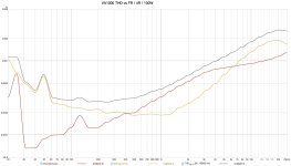
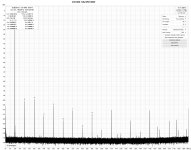
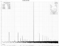
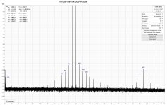
Please tell me what software you use to perform the distortion measurement?
Thank you in advance.
Thank you in advance.
yes its REW...
meanwhile I finished the second amp 🥈 💪 and tested remote on-off function, particulary synchronisation of both. They are synced and timed via mains frequency, however the second one switches one cycle later as trigger is powered from the psu of first one. So there is difference of about 20-30ms but visually it looks like synced. (if you play the clip slowed down you can see the delay)
What is amazing, I was able to tweak soft-starting of both amps so they can start from same power outlet at once and not trigger breaker 🙂
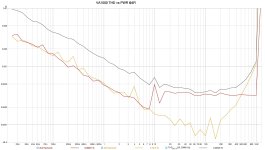
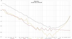
also I managed to make balanced floating voltage divider and tried to measure THD vs Power. I think I am still limited by my gear capabilities as for source I am using focusrite solo and this amp wants rly high input voltage (2,5Vrms) but still measures nicely 🙂 maybe if I upgrade my soundcard I will update results in future...
below is thd vs pwr into 8R load (data below graph corresponds to minimal values ~45W)

after some time and testing I have decided to upgrade the control module. What has changed:
Mechanical changes:
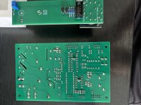
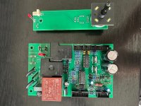
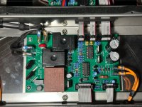
Electrical changes:

Made a new mini PCB for "meter switch" which apart rotating switch now includes:

Here is short clip how auto-brightness control works with LDR (but not used it yet)
camera auto-brightness makes it tricky to capture but you get the idea... 😀
Mechanical changes:
- PCB is slightly wider so I was able to rotate SMPS and optimise mains powered components layout
- mains power lines are 2-layer (top+bottom) for better current handling
- wider mains isolation gaps including milled gaps against safe low voltage side
- NTC power thermistors with cooling gaps in PCB and slightly moved away of other components so they have more air to cool
- optimised IC power lines, peripherals and grounding


Electrical changes:
- positive psu for VU log amp is delayed and powered via pnp transistor (similar as original mac has it) At first it was not needed in my application, however after tweaking meters and lowering meter resistances, they got ugly punch when turning on, this is now fixed.
- dual opto is replaced with single mini one so only mains frequency is now optocoupled.
- "remote on" signal is powered directly from SMPS "digi" part of PSU via pnp transistor from power relay directly, resulting in zero delay for second amp turn on. Power up of both at the same time is still soft enough, and breaker holds it without any problems.
- also mute relay is powered from smps to simplify connections
- better filtering of comparator inputs for temp control to prevent any false triggering

Made a new mini PCB for "meter switch" which apart rotating switch now includes:
- standby led (not using it as I have not drilled panel on that spot {yet} but in case I will decide I need it in future its going to be there prepared 😉 )
- regulated constant current sink for meter backlight directly located on this board, so trim pot is easily available from top and brightness can be regulated
- parallel to this current sink is also pin header for LDR = I was thinking to use light dependent control for front meter brightness as meters are quite bright during evening. The LDR would be located in the middle part of front panel top cover. After some testing I figured out I am satisfied just with one fixed value that fits all scenarios so I will not use this feature, but just in case I change my mind its there prepared and easily accessible 😎

Here is short clip how auto-brightness control works with LDR (but not used it yet)
camera auto-brightness makes it tricky to capture but you get the idea... 😀
Last edited:
