A few months ago I have started building new amp and this is going to be another build thread for sharing my progress....
As naming suggests its going to be >1kw amp, design will be similar to the McIntosh 1.25kw amps but majority is going to be designed by myself from scratch.
Amplifier part:
It will be bridged monoblock = two separate amps in one chassis which feeds one common autotransformer with floating output. I have already successfully built this concept in my “MC502” and liked it very much.
Each amplifier is going to be fully balanced classic, nothing new or special. Input diff populated with ONsemi 2n5551/5401, Voltage amp stage uses fast KSA1381/KSC3503 with local compensation to tweak square as needed. As pre-drivers I want to try use Toshibas TTA/TTC004. As drivers classic and powerful MJE15032/33. No need to use anything extra fast here as everything is quite slowed down and compensated to match output transformers anyway. Drivers will feed 8 pairs of MJL1302/3281. Power supply voltage is going to be about 2x65Vdc and each amp will drive approx. 2,7R load.
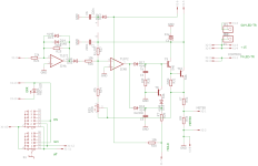
Schematic:
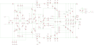
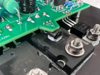
Output stage transistors are split to two separate heatsinks, 4 pairs on each. PCBs are going to be interconnected with locking type IDC ribbon cable which connects main drive as well as temp protection sensor. Bias sensing is only on one PCB done by small to92 transistor sitting flat, directly in the middle of output transistor on top of the package. I plan to stick it there with thermal grease and whole assembly with PCB will force it to sit flat in there. This should provide quite quick and effective thermal sensing and bias tracking.
I have tweaked PCB layout and all the feedback sensing on amps PCBs the best I could to mix all the feedback from both split PCBs + output transformer, well the output terminals - so even the internal wiring is compensated 😉 Power traces are laid on PCB borders around for minimal effect on audio paths, with local low-esr blocking for each output transistor separately. Power and signal grounds are completely separate and going to be connected with separate conduit to main caps, the central ground.
Both PCBs of one amp are mirrored so all NPN/PNP output transistors are going to be on the same side when PCBs are oriented against each-other. This should ease up all the wiring. Below are a few pics of amp pcb:
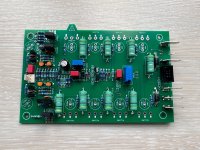
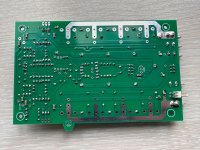
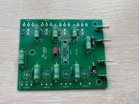
(its still work in progress and don't have all the parts yet)
Audio inputs
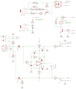
are on small extra PCB which enables the use of balanced or unbalanced signal similar to mac amps. There is small switch for selecting the input used. As invertor I am planning to use OPA1611 as I feel that one is going to be most neutral of all. I want to make it as good as possible so I incorporated PP audio input caps, to fit them somewhere, they are going to be populated on the bottom side of the board. On this small board there is also small relay for audio mute, which shorts the inputs when amp turns on/off. There is also opto-isolated remote possibility to turn on/off the amp remotely.
This board also basically makes the common audio input ground of the amps (10k), the 100k input resistors directly on amp boards are basically just prevention for cable faulty.
Schematic:
PCB:

...continuing...
Control module
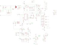
I was designing this part the longest, as it contains many functions and two completely isolated power supplies on quite tight layout. All the functions are done in old-school way, without need of MCU, for easy service and reliability.
My first idea was to use triac for switching and no standby at all to save energy. However to maintain some protection circuits to operate even in off state I had to use standby. To make it as effective as possible and not incorporate extra electromagnetic hum of small transformer I decided to use small SMPS in layout of potted EI transformer. I used 5W SMPS with 12VDC output to power main power relays, and there is simple +5V regulator to power remaining protection circuits.
Power consists of 3 states, similar to mac amps... so the wiper of the rotary switch is connected to transistor base which switch main power 30A relay. The transistor base is either grounded(off), connected to +5V rail via optocoupler (remote) or connected directly to +5V rail(on).
When turn-on, main power transformer is soft-started by 2x22R NTC power thermistors. These are so high in value on purpose, so turn-on limits current as much that its possible to turn on two monoblocks at the same time, even from one power socket. In mains circuit there is also protection varistor and X2 filter nearby smps for better filtering.
After turn on, main power transformer low-power accessory winding creates balanced power supply for opamps and other circuits. Also from the AC side, the AC is used as clock generator feeding optocoupler. This transfers CLK signal to binary counter CD4040. Counter reset is connected to main power relay transistor collector. When turned on, the reset is grounded and counter starts counting mains frequency. I used mains CLK for perfect synchronisation of two different monoblocks. Third binary counter output is used as clk divider and blinking LED (protect) indicating soft-starting the amp. After about 2,5 seconds another power relay shorts power thermistors. After another 2,5s the second relay stays turned on via diodes and audio mute relay is unmuted. The protect LED stops blinking.
Along that, whole time are powered other protection circuits:
There is temp protection by comparator LM339 with 4x LM35 temp sensors, one in each heatsink. They all share one common hysteresis, after reaching 80 degrees celsius, comparator shorts base of power relay transistor and turns everything off. While doing so, protection LED cathode is also grounded indicating error on front panel. Amp is going to be blocked and cannot be turn on till temp falls down to 50 degrees.
Schematic:
PCB:
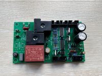
Control module
I was designing this part the longest, as it contains many functions and two completely isolated power supplies on quite tight layout. All the functions are done in old-school way, without need of MCU, for easy service and reliability.
My first idea was to use triac for switching and no standby at all to save energy. However to maintain some protection circuits to operate even in off state I had to use standby. To make it as effective as possible and not incorporate extra electromagnetic hum of small transformer I decided to use small SMPS in layout of potted EI transformer. I used 5W SMPS with 12VDC output to power main power relays, and there is simple +5V regulator to power remaining protection circuits.
Power consists of 3 states, similar to mac amps... so the wiper of the rotary switch is connected to transistor base which switch main power 30A relay. The transistor base is either grounded(off), connected to +5V rail via optocoupler (remote) or connected directly to +5V rail(on).
When turn-on, main power transformer is soft-started by 2x22R NTC power thermistors. These are so high in value on purpose, so turn-on limits current as much that its possible to turn on two monoblocks at the same time, even from one power socket. In mains circuit there is also protection varistor and X2 filter nearby smps for better filtering.
After turn on, main power transformer low-power accessory winding creates balanced power supply for opamps and other circuits. Also from the AC side, the AC is used as clock generator feeding optocoupler. This transfers CLK signal to binary counter CD4040. Counter reset is connected to main power relay transistor collector. When turned on, the reset is grounded and counter starts counting mains frequency. I used mains CLK for perfect synchronisation of two different monoblocks. Third binary counter output is used as clk divider and blinking LED (protect) indicating soft-starting the amp. After about 2,5 seconds another power relay shorts power thermistors. After another 2,5s the second relay stays turned on via diodes and audio mute relay is unmuted. The protect LED stops blinking.
Along that, whole time are powered other protection circuits:
There is temp protection by comparator LM339 with 4x LM35 temp sensors, one in each heatsink. They all share one common hysteresis, after reaching 80 degrees celsius, comparator shorts base of power relay transistor and turns everything off. While doing so, protection LED cathode is also grounded indicating error on front panel. Amp is going to be blocked and cannot be turn on till temp falls down to 50 degrees.
Schematic:

PCB:

I will describe transformers later when I get them, but continuing with PSU board...
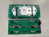
Power transformer secondary is going to be rectified by big square, well cooled, 50A bridge rectifier, from there to main PSU crew-type caps. I am still deciding which to order and hesitating between some Nichicon and Kemet. Kemet offers way longer lifespan and higher ripple current ratings so I will probably use those, the 2x62mF/100V caps, still deciding. To avoid extra costs for cap holders I want to hold them by PCB mainly, which will hang inside of chassis, and caps will go thru chassis out thru another 3d printed holders of some sort.
PCB has copper on both sides for better current rating as well as without sodlermask from the bottom, so I can solder some thicker wires around main conduits. I have implemented here blown fuse detector. As all the power is quite high, I wanted to prevent any further damage or fire. Whenever any of the fuses will blow, the optocouplers will trigger simple latch circuit, which shorts base of on/off transistor. This shuts off whole amp. This triggering will light red led on front panel indicating error and prevents turn on. The error continues until mains power is disconnected...
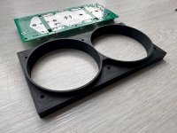
VU log amp
this is mostly original mcintosh circuit, where I can very nicely tweak hold and release times, as well as sensitivity of logarithm. I am going to use only voltage sensing of one half of the bridge for practical reasons, so no current sensing... (I wanted to avoid guiding main signal thru measurement current transformer core, not sure why but I somehow dislike that 😀 )
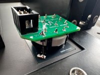
For easier mechanical assembly and less wiring I have implemented also one of the rotary switches including backlight on the PCBs. Same for other rotary switch for meters functions switching (hold, off, watts)
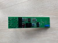
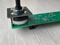
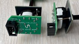
next up, BIG!!! VU meters...
Power transformer secondary is going to be rectified by big square, well cooled, 50A bridge rectifier, from there to main PSU crew-type caps. I am still deciding which to order and hesitating between some Nichicon and Kemet. Kemet offers way longer lifespan and higher ripple current ratings so I will probably use those, the 2x62mF/100V caps, still deciding. To avoid extra costs for cap holders I want to hold them by PCB mainly, which will hang inside of chassis, and caps will go thru chassis out thru another 3d printed holders of some sort.
PCB has copper on both sides for better current rating as well as without sodlermask from the bottom, so I can solder some thicker wires around main conduits. I have implemented here blown fuse detector. As all the power is quite high, I wanted to prevent any further damage or fire. Whenever any of the fuses will blow, the optocouplers will trigger simple latch circuit, which shorts base of on/off transistor. This shuts off whole amp. This triggering will light red led on front panel indicating error and prevents turn on. The error continues until mains power is disconnected...


VU log amp
this is mostly original mcintosh circuit, where I can very nicely tweak hold and release times, as well as sensitivity of logarithm. I am going to use only voltage sensing of one half of the bridge for practical reasons, so no current sensing... (I wanted to avoid guiding main signal thru measurement current transformer core, not sure why but I somehow dislike that 😀 )
For easier mechanical assembly and less wiring I have implemented also one of the rotary switches including backlight on the PCBs. Same for other rotary switch for meters functions switching (hold, off, watts)


next up, BIG!!! VU meters...
It is nearly impossible to get large analog VU meters in today's digital age... 🥹 Even one of the oldest local analog panel meter manufacturer in EU does not have such a big ones in stock and making custom on order would be extremely expensive. My first plan was to buy smaller meters and just change the needle for a longer one and use the motor assy to build larger meters. However meter mechanism appeared to be much more delicate and balanced than I expected and even tiny amount of dispabalnce had serious impact on performance. I didn't know what to do, so I considered using a small stepper motor and an ADC with a processor that would convert the analog voltage level to the angle of rotation of the motor. It would probably work quite well and I already had something on paper, but I really didn't want to put abything digital into such a "retro" amplifier.
At least, finally, ... after a long search, I discovered an imitation of Mac VU meters on ebay that have 20cm!!! it is branded as "P-200" and I bought them basically only for motor assy and needle 😀 They were quite expensive, but are absolutely amazing - they have a very stiff spring and a very strong motor. Despite the fact that they have a very long needle (11cm), they are ultra fast.
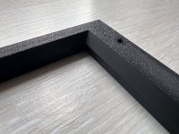
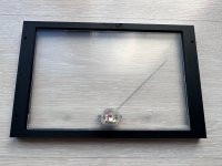
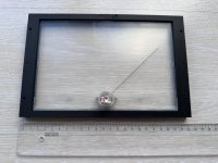
I used the motor from the meters as a basis for further modification. The needle with the motor was finally big enough, but the whole background had the potential to be even bigger and better looking. I wanted the gauges to be as big as possible, and I didn't want a plastic window. So I completely disassembled meters and built my own little house frame printed on a 3D printer around the mechanism of these gauges.
I will put real glass in front and of course also the actual calibrated background corresponding to the amplifier's performance(>1kw). The glass will be inserted into a milled pocket from the back of the panel and held by a frame that also holds the entire mechanism and the gauge background. I ordered new scale prints, silk-printed on ultra thin plexi with diffuse foil stick on back, which replaces the previous original chinese, blue one. A few photos of the assembly below:
3dprinted frame:
New scale with stock backlight:
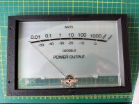
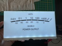
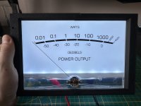
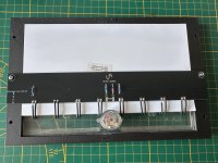
On back there is narrow PCB to hold everything in place, and also connect all LEDs and meter motor. From there just a 6pin IDC will go to log amp board:
At least, finally, ... after a long search, I discovered an imitation of Mac VU meters on ebay that have 20cm!!! it is branded as "P-200" and I bought them basically only for motor assy and needle 😀 They were quite expensive, but are absolutely amazing - they have a very stiff spring and a very strong motor. Despite the fact that they have a very long needle (11cm), they are ultra fast.
I used the motor from the meters as a basis for further modification. The needle with the motor was finally big enough, but the whole background had the potential to be even bigger and better looking. I wanted the gauges to be as big as possible, and I didn't want a plastic window. So I completely disassembled meters and built my own little house frame printed on a 3D printer around the mechanism of these gauges.
I will put real glass in front and of course also the actual calibrated background corresponding to the amplifier's performance(>1kw). The glass will be inserted into a milled pocket from the back of the panel and held by a frame that also holds the entire mechanism and the gauge background. I ordered new scale prints, silk-printed on ultra thin plexi with diffuse foil stick on back, which replaces the previous original chinese, blue one. A few photos of the assembly below:
3dprinted frame:


New scale with stock backlight:


On back there is narrow PCB to hold everything in place, and also connect all LEDs and meter motor. From there just a 6pin IDC will go to log amp board:

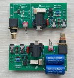
As I was designing case I realised because of very tall main capacitors input board would not fit as I planned. So I needed to redesign input board to make it fit in a bit different way. Finally the input board is finalised including opa1611 and fancy audio pp caps:
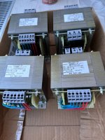
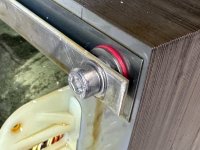
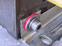
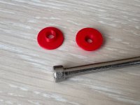
Meanwhile I have received mains transformers. Its 1,1kw with multiple primary taps to fit better to nowadays 240V grid. The core is EI150/93 = core size 50x93mm with M111 0,35mm oriented silicon steel. The core saturated a bit and no-load power draw was about 60W and laminations were slightly audible as such a thin laminations are tricky to dampen even tho transformer is impregnated. I have figured out there are simple iron screws in core which are magnetic basic iron material and this degrated core properties as well as shorted top/bottom laminations. So I tuned my trannies with A4 grade stainless steel screws (non-magnetic and very strong material) including 3D printed insulating washers. Thanks to this tuning I was able to tighten laminations with way way way greater force as well as insulated it and not incorporating cheap magnetic element within core. I was able to decrease the standby power of transformer to increadible 18W!!! wich is 3-4x lower than original value. Core loss is now just 1,6% 🙂 Ofc it is also not hummy any more 🎉
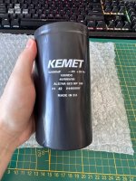
Also big caps arrived 💪
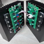
I have noticed I forgot to post pics of finished amp boards, so here they are:
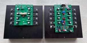
The boards are going to be facing against each other like this, the bias trim pot is angled one accessible from top and also small 2pin molex to read biac current:
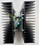
I have used unique way of temp reading for bias current, the board contains notch, below which is small to92 laying flat on top of power transistor. The connection is tight and heat transfer is excellent. Bias tracking is extremely fast and reliable this way:
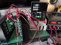
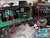
First testing, gladly everything works fine ♥️ my lab power supply has its limits but at least I was able to test basic functionality:
Next coming soon... output auto-transformers 😎

Meanwhile I have received mains transformers. Its 1,1kw with multiple primary taps to fit better to nowadays 240V grid. The core is EI150/93 = core size 50x93mm with M111 0,35mm oriented silicon steel. The core saturated a bit and no-load power draw was about 60W and laminations were slightly audible as such a thin laminations are tricky to dampen even tho transformer is impregnated. I have figured out there are simple iron screws in core which are magnetic basic iron material and this degrated core properties as well as shorted top/bottom laminations. So I tuned my trannies with A4 grade stainless steel screws (non-magnetic and very strong material) including 3D printed insulating washers. Thanks to this tuning I was able to tighten laminations with way way way greater force as well as insulated it and not incorporating cheap magnetic element within core. I was able to decrease the standby power of transformer to increadible 18W!!! wich is 3-4x lower than original value. Core loss is now just 1,6% 🙂 Ofc it is also not hummy any more 🎉


Also big caps arrived 💪

I have noticed I forgot to post pics of finished amp boards, so here they are:

The boards are going to be facing against each other like this, the bias trim pot is angled one accessible from top and also small 2pin molex to read biac current:


I have used unique way of temp reading for bias current, the board contains notch, below which is small to92 laying flat on top of power transistor. The connection is tight and heat transfer is excellent. Bias tracking is extremely fast and reliable this way:

First testing, gladly everything works fine ♥️ my lab power supply has its limits but at least I was able to test basic functionality:


Next coming soon... output auto-transformers 😎
Last edited:
The output transformer is EI120/73 = core 40x73mm, thin 0.35mm magnetically oriented silicon steel laminations. For the best core properties it is without screws, only impregnated. The coil bobbin is divided into two equal mirror halves, wound in opposite directions so that the halves are exactly the same, but so that it is one continuous winding:
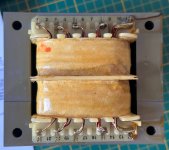
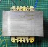
I was calculating transformer for ~2 months over nights around the xmas time, until I got all values absolutely excellent. There is absolutely perfect filling in bobbin = each section contains needed number of turns and its always exact so the layer is always wound completely from edge to edge. In case I needed to increase filling for particular layer I have used dual enameled wire. Thanks to this, its also not needed to used interlayer insulation for layers where >40V is reached. There is a lot of wire and it was needed to wind it very precisely to make fit between laminations window. Production company where I ordered these told me, they needed to tap/hammer sections of thick wire to make them flat after winding to make it fit.
I arranged the windings/sections in a way that the most current loaded section (4Ω) is wound as first on core. The reason is so that it is as short as possible for lowest possible resistance and at the same time it creates a "primary" for the core, for the best possible control over core. The secondary winding is next and is divided into two sections, between which the 8R winding is wound. Thanks to this, the winding for 8Ω, where it is actually transformed the most, is covered from both sides by a large number of turns of the secondary winding of the autotransformer. I don't have tap exactly in the middle point between 4Ω and 8Ω but slightly moved towards 4Ω. This is because of several reasons but the main one is winding filling and also load current requirements of respective windings.
The overall layering / sections could be divided even more than I projected, (after each winded layer, not section) and leakage inductance could be even lower, however from my previous experience I know that it could potentially bring more problems than benefits. Below is the sketch of transformer sections:
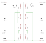
Winding must have been quite complicated because very thick wires layer on relatively thin wire, so that the turns do not fall into each other, each section is covered with thin flattening material.
For 4Ω there is bifilar parallel 2x 1.7mm wire
For 8Ω it is bifilar parallel 2x1.5mm
The autotransformer common/secondary winding is 1.06mm
Despite the fact that it is an efficient autotransformer and hi-fi use, I have used relatively low current density (3.4A/mm^2), thanks to the significantly oversized core. According to my calculations, the transformer should handle approximately 25Hz at 1000W, I am really curious what will the real value be 🙂
During early testing, I wanted to see how voltage limitation will look like, and it creates nice tube-like rounded limit 🙂
I am still jus ton test bench lab power supply so no full loading yet, but 10k square looks nice, but slow - as expected. However it is exceptionally stable against capacitive loading of the output:
(clicking sound in video is switch when I connect 470nF capacitor on output)
I tried to tune the slew rate as it was truly very slow to my taste, so tried several different negative feedback connections and compensations but non of that worked. I tried to tweak amount / ratio of feedback directly fed from amp vs autotransformer and it didn't help either.
(just to note, original mac takes about 1,4:1 feedback from amp/transformer) I have used 1:1 ratio so transformer is compensated by feedback a bit more what could help to lower distortion.
After I figured slew rate is significantly limited even without transformer the problem was in amp itself. I projected it too much on a safe side and made it too slow. So I removed local comp of VAS stage and it goes! and its stable! 😀 I think it needs further tuning as on analogue oscilloscope I see very small instability but just a few pico farads should do the trick.
Long-story-short I have got 60V/us even with output transformer 🙂 bandwidth with this setting is about 170kHz@-3dB but will lower it a bit as mentioned above in final tuning. I don't have such a tiny hi-voltage caps on hand atm so will get back to that soon...
(just with 2x60V lab supply for now)


I was calculating transformer for ~2 months over nights around the xmas time, until I got all values absolutely excellent. There is absolutely perfect filling in bobbin = each section contains needed number of turns and its always exact so the layer is always wound completely from edge to edge. In case I needed to increase filling for particular layer I have used dual enameled wire. Thanks to this, its also not needed to used interlayer insulation for layers where >40V is reached. There is a lot of wire and it was needed to wind it very precisely to make fit between laminations window. Production company where I ordered these told me, they needed to tap/hammer sections of thick wire to make them flat after winding to make it fit.
I arranged the windings/sections in a way that the most current loaded section (4Ω) is wound as first on core. The reason is so that it is as short as possible for lowest possible resistance and at the same time it creates a "primary" for the core, for the best possible control over core. The secondary winding is next and is divided into two sections, between which the 8R winding is wound. Thanks to this, the winding for 8Ω, where it is actually transformed the most, is covered from both sides by a large number of turns of the secondary winding of the autotransformer. I don't have tap exactly in the middle point between 4Ω and 8Ω but slightly moved towards 4Ω. This is because of several reasons but the main one is winding filling and also load current requirements of respective windings.
The overall layering / sections could be divided even more than I projected, (after each winded layer, not section) and leakage inductance could be even lower, however from my previous experience I know that it could potentially bring more problems than benefits. Below is the sketch of transformer sections:

Winding must have been quite complicated because very thick wires layer on relatively thin wire, so that the turns do not fall into each other, each section is covered with thin flattening material.
For 4Ω there is bifilar parallel 2x 1.7mm wire
For 8Ω it is bifilar parallel 2x1.5mm
The autotransformer common/secondary winding is 1.06mm
Despite the fact that it is an efficient autotransformer and hi-fi use, I have used relatively low current density (3.4A/mm^2), thanks to the significantly oversized core. According to my calculations, the transformer should handle approximately 25Hz at 1000W, I am really curious what will the real value be 🙂
During early testing, I wanted to see how voltage limitation will look like, and it creates nice tube-like rounded limit 🙂
I am still jus ton test bench lab power supply so no full loading yet, but 10k square looks nice, but slow - as expected. However it is exceptionally stable against capacitive loading of the output:
(clicking sound in video is switch when I connect 470nF capacitor on output)
I tried to tune the slew rate as it was truly very slow to my taste, so tried several different negative feedback connections and compensations but non of that worked. I tried to tweak amount / ratio of feedback directly fed from amp vs autotransformer and it didn't help either.
(just to note, original mac takes about 1,4:1 feedback from amp/transformer) I have used 1:1 ratio so transformer is compensated by feedback a bit more what could help to lower distortion.
After I figured slew rate is significantly limited even without transformer the problem was in amp itself. I projected it too much on a safe side and made it too slow. So I removed local comp of VAS stage and it goes! and its stable! 😀 I think it needs further tuning as on analogue oscilloscope I see very small instability but just a few pico farads should do the trick.
Long-story-short I have got 60V/us even with output transformer 🙂 bandwidth with this setting is about 170kHz@-3dB but will lower it a bit as mentioned above in final tuning. I don't have such a tiny hi-voltage caps on hand atm so will get back to that soon...
(just with 2x60V lab supply for now)
Last edited:
Awesome job, what a beast of an amplifier.
Will you ever put it at full power? With hearing protection, though.
By the way, can you tell me the company that prints the meters?.
Will you ever put it at full power? With hearing protection, though.

By the way, can you tell me the company that prints the meters?.
widi thanks
power ... probably not 🙂
meters plexi was printed by local advertisement print company, its my neighbour next street, not sure even what the official company name is 😆
power ... probably not 🙂
meters plexi was printed by local advertisement print company, its my neighbour next street, not sure even what the official company name is 😆
maconi118 there are some advantages but also disadvantages ofc... its just different / old school / way of doing things. A few of advantages:
I think the major one - incredible stability against capacitive and complex loads, which real speaker crossovers are
also to note, its auto-transformer, which is way more effective than standard galvanically isolated transformer. You transform only portion of power change, not all power.
- same power to 4R and 8R
- no need for DC protect (if output sees DC it will short thru transformer common winding to gnd and blow the power fuse if its serious)
- I can pick what "input impedance" or ratio of the autotransformer is and scale SOA of output transistors ways more effectively
- you can make big power with way lower power supply voltage
- with lower psu voltage you can use higher bias currents for the same amount of power compared to standard amp with lower overall power loss
- in case its bridged amp (quad balanced as mac calls it) you have a lot of CMRR directly in output transformer, not only on load itself
- nice soft voltage clipping similar to classic tube amps, but with all advantages and properties of silicon amp.
I think the major one - incredible stability against capacitive and complex loads, which real speaker crossovers are
also to note, its auto-transformer, which is way more effective than standard galvanically isolated transformer. You transform only portion of power change, not all power.
thanks a lot for this extensive explanation! and compliments for your great project and description.
would it make sense to use autotransformer amp for bass let's say up to 1khz ans standard amp for tweeter in a biamp set-up?
in this case the autotransformer could be standard 60Hz one? 110 to 220v for example?
would it make sense to use autotransformer amp for bass let's say up to 1khz ans standard amp for tweeter in a biamp set-up?
in this case the autotransformer could be standard 60Hz one? 110 to 220v for example?
Last weeks I was tweaking the amp's performance. I was trying to lower pre-driver compensation even lower (22p) but it was self-oscillating around 4Mhz and not even boucherot helped. So I went back to 47p + added 2p2 to VAS just for peace of mind. It still keeps 60V/us and is very nice and stable.
I was also further testing the effect of feedback ration between local amp feedback vs transformer feedback. If I tried 1,4:1 (as original mac) it was very slow and square wave looked very rounded. Maybe original mac transformers are better with lower leakage inductace and thats why, who knows. But mac amps are slower in general som maybe they did not push it where it is not necessary. Long-story short, by changing this ratio it is possible to very nicely tweak step response so I used 1:1 from amps vs transformer. The results so far what I've got is below (this is just one amp module, no bridge yet, 10k square)
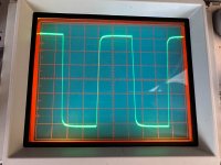
After everything was tuned to my liking, I have finally finished all modules 🎉 💪 😎
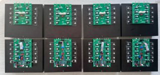
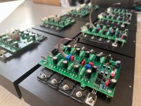
Meanwhile I have received all the mechanical and steel parts, and there are lots! I draw all parts directly as flat in autocad no 3d and simulations, gladly everything fits nicely. Everything is made on order in local steel workshop that I have in nearby village, all parts are laser cut, cnc bent and some powder coated...
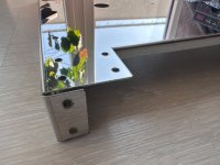
So the first one, main chassis below. Polished stainless steel, why stainless you might say .... because it's non magnetic, and will not spread transformer hum everywhere:
(its not fully cleaned from protection film yet, so there might be some defects visible on photos, those are glue residues)
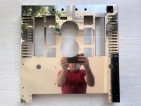
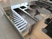
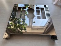
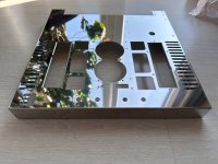
Inside... please notice the "notch", that one is for small 2pin molex for bias check:
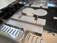
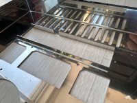
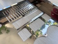
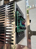
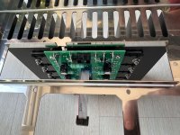
Heatsinks with driver PCBs are hotter than the ones without, so those are located on outer sides of chassis for better cooling.
Bottom cover:
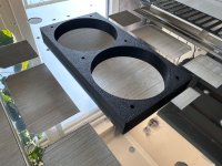
Below you can see 3D printed main capacitors holders, the capacitors are going to be held by their connections but to avoid insulation damage against steel, its sort of protector and also to avoid resonance. They are quite "exact" with 0,1mm tolerance so fits nice and tight to caps.
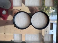
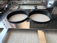
Here is middle rear panel for input board. Also this part covers the main psu caps:
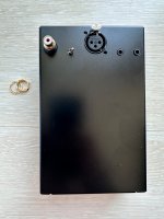
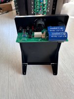
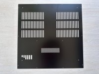
The opposite of that panel is very same, just without holes. The dome is going to be covered with following fancy ventilated cover:
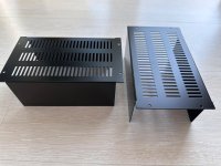
and as I am limited with how many images I can upload I will continue in next post 😀
I was also further testing the effect of feedback ration between local amp feedback vs transformer feedback. If I tried 1,4:1 (as original mac) it was very slow and square wave looked very rounded. Maybe original mac transformers are better with lower leakage inductace and thats why, who knows. But mac amps are slower in general som maybe they did not push it where it is not necessary. Long-story short, by changing this ratio it is possible to very nicely tweak step response so I used 1:1 from amps vs transformer. The results so far what I've got is below (this is just one amp module, no bridge yet, 10k square)

After everything was tuned to my liking, I have finally finished all modules 🎉 💪 😎


Meanwhile I have received all the mechanical and steel parts, and there are lots! I draw all parts directly as flat in autocad no 3d and simulations, gladly everything fits nicely. Everything is made on order in local steel workshop that I have in nearby village, all parts are laser cut, cnc bent and some powder coated...
So the first one, main chassis below. Polished stainless steel, why stainless you might say .... because it's non magnetic, and will not spread transformer hum everywhere:
(its not fully cleaned from protection film yet, so there might be some defects visible on photos, those are glue residues)


Inside... please notice the "notch", that one is for small 2pin molex for bias check:


Heatsinks with driver PCBs are hotter than the ones without, so those are located on outer sides of chassis for better cooling.

Bottom cover:

Below you can see 3D printed main capacitors holders, the capacitors are going to be held by their connections but to avoid insulation damage against steel, its sort of protector and also to avoid resonance. They are quite "exact" with 0,1mm tolerance so fits nice and tight to caps.


Here is middle rear panel for input board. Also this part covers the main psu caps:


The opposite of that panel is very same, just without holes. The dome is going to be covered with following fancy ventilated cover:

and as I am limited with how many images I can upload I will continue in next post 😀
Last edited:
These are inner chassis braces, they will be mounted directly below transformers to avoid bending:
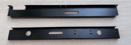
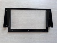
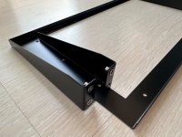
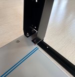
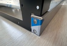
This is front panel holder, I have used rivet nuts for easier mount, fits very nicely. When it sits on top of chassis, bottom bends are nicely aligned... 😎
I dont have front panel yet, still waiting, but below is front mount cover:
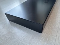
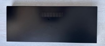
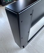
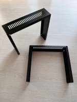
Here are heatsink cover parts:
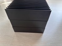
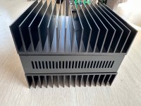
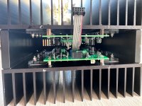
And... the most critical part I was afraid the most: transformer covers. It was very tricky for manufacturer as the bend walls are longer than the base dimensions of the boxes. The box is one piece of 1,2mm bent metal, and walls are welded in corners so the box is water-tight. The welds are sanded and everything powder coated. In my opinion result is excellent and looks like one moulded piece of metal. You cannot even see welds or any imperfections. These custom boxes are absolutely top and they are CNC exact! it fits to main chassis like lego and all bends are absolutely precise and right angles...
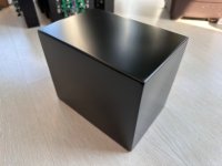
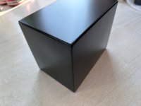
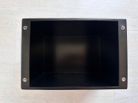
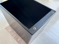
I have used stainless riv nuts again for these^^
below is how it sits on chassis, just test fit:
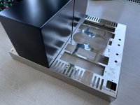
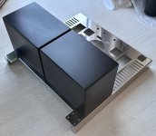
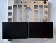
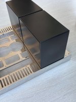
I think the next is going to be transformers potting and putting parts slowly together...

This is front panel holder, I have used rivet nuts for easier mount, fits very nicely. When it sits on top of chassis, bottom bends are nicely aligned... 😎


I dont have front panel yet, still waiting, but below is front mount cover:


Here are heatsink cover parts:


And... the most critical part I was afraid the most: transformer covers. It was very tricky for manufacturer as the bend walls are longer than the base dimensions of the boxes. The box is one piece of 1,2mm bent metal, and walls are welded in corners so the box is water-tight. The welds are sanded and everything powder coated. In my opinion result is excellent and looks like one moulded piece of metal. You cannot even see welds or any imperfections. These custom boxes are absolutely top and they are CNC exact! it fits to main chassis like lego and all bends are absolutely precise and right angles...


I have used stainless riv nuts again for these^^
below is how it sits on chassis, just test fit:


I think the next is going to be transformers potting and putting parts slowly together...
Last edited:
I wouldn't dream of going into this, it reminds me of 110V radio wiring, sounds like a trumpet 🤣
Great work on the very refined chassis.
Why build this type of chassis instead of a more conventional one? Obviously, this construction is more expensive.
Regards👍
Why build this type of chassis instead of a more conventional one? Obviously, this construction is more expensive.
Regards👍
Widi I like the way original mac is made and it makes sense in many ways so I follow that design.
Not sure that this style of chassis is more expensive compared to conventional designs, very same imo
Not sure that this style of chassis is more expensive compared to conventional designs, very same imo
Slowly putting things together ... The PSU board has copper from both sides, however I have reinforced it even further from bottom unmasked side with 6mm^2 copper rods and thin copper plates:
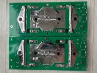
Mounted in chassis, top view with 3d printed cap holder:
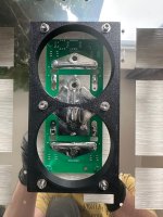
inside the chassis it looks like this:
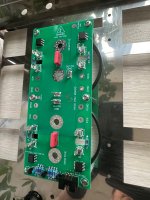
With caps test-fitted below...
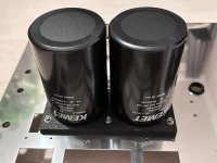
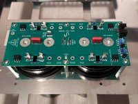

Mounted in chassis, top view with 3d printed cap holder:

inside the chassis it looks like this:

With caps test-fitted below...


Front panels arrived today 🥳 so I tried to complete one, and thanks to all measured to perfection. it was very straightforward 🙂
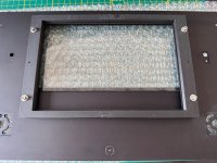
as first I have covered edges of glass with thin textile tape. (I cut the glass from photo clip frame), here is how it fits in milled cutout from back side in black anodized aluminium panel:
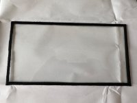
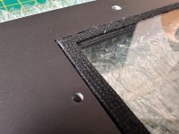
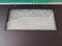
The glass is held in place by 3d printed frame I have already mentioned in my #4 post
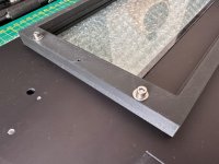
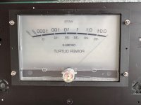
I have inserted meter assembly with new scale and wired all remaining connections for backlight etc...
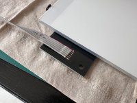
meter assy completed + mounted steel frame for holding the panel:
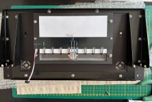
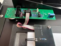
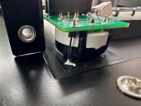
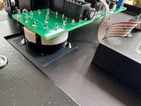
Internal connection of switches, log amp board and the LED backlit boards, note how they sit flush in milled pockets from back of the panel:
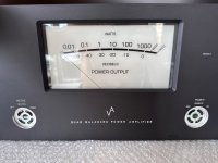
Knobs mounted and panel completed, also tested how the backlight looks like 😎
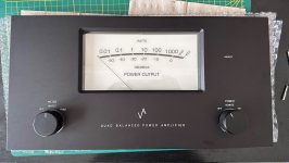
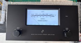
Knobs are backlit as well, however it is not visible as much during daylight, (on above images they are not lit yet)
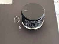
next up... chassis assembly and transformers potting! 😱
as first I have covered edges of glass with thin textile tape. (I cut the glass from photo clip frame), here is how it fits in milled cutout from back side in black anodized aluminium panel:


The glass is held in place by 3d printed frame I have already mentioned in my #4 post


I have inserted meter assembly with new scale and wired all remaining connections for backlight etc...


meter assy completed + mounted steel frame for holding the panel:


Internal connection of switches, log amp board and the LED backlit boards, note how they sit flush in milled pockets from back of the panel:


Knobs mounted and panel completed, also tested how the backlight looks like 😎


Knobs are backlit as well, however it is not visible as much during daylight, (on above images they are not lit yet)

next up... chassis assembly and transformers potting! 😱
- Home
- Amplifiers
- Solid State
- VA1000 monoblocks with auto-transformer output
