Hi everyone,
I'm a newbie at audio amplifiers and studing from Randy Slone's book I've seen that the most common VA topologies are:
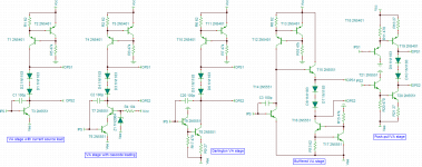
-VA stage with current source load;
-Cascode VA stage;
-Darlington VA stage;
-Differential VA stage;
-Bootstrapped VA stage;
-Buffered VA stage;
-Push-pull VA stage.
The VA stage with current source load is the most common topology and one of the best topologies, it uses a driver transistor connected to the inverting side of the differential stage, a current source and some kind of voltage source for biasing the drivers and/or the output stage (could be implemented with diodes, a resistor, or a VBE multiplier).
The cascode VA stage uses common base topology to load current in the VA stage and it's also a good topology.
Darlington VA stages are referenced as "the best" in some audio amplifier books, they can be implemented with cascode loading and they have a larger voltage gain.
Differential VA stage (I don't know much about this topology), but I think that's not a good ideia because differential pairs act as transconductance amplifiers and not as transimpedance amplifiers.
Bootstraped VA stage uses positive feedback coming from a RC network connected to the output to load the VA stage, I don't know much about this technology, but seems interesting, some authors consider this topology to be a poor one, it's one of the most common VA topologies in audio ICs such as some TDA series and STK series. Does anyone knows exactly how this topology works?
Buffered VA stage uses a complementar stage after the VA stage to act as voltage buffer, the only idea is to increase the output current of the VA stage (????)
Push-pull VA topology uses two driver transistors in darlington configuration or not, they are only used in "mirror image amplifiers", generally due to nonlinearities between the NPN devices and PNP devices the "mirror image amplifiers" suffers from quiescent bias instability (one device could draw more current than the other one) the differential stage has to have collector resistors or a current mirror with active loading (????).
The purpose of this post is to know which of those topologies are " the best".
Thank you very much for your attention,
Best regards,
Daniel Almeida
I'm a newbie at audio amplifiers and studing from Randy Slone's book I've seen that the most common VA topologies are:
-VA stage with current source load;
-Cascode VA stage;
-Darlington VA stage;
-Differential VA stage;
-Bootstrapped VA stage;
-Buffered VA stage;
-Push-pull VA stage.
The VA stage with current source load is the most common topology and one of the best topologies, it uses a driver transistor connected to the inverting side of the differential stage, a current source and some kind of voltage source for biasing the drivers and/or the output stage (could be implemented with diodes, a resistor, or a VBE multiplier).
The cascode VA stage uses common base topology to load current in the VA stage and it's also a good topology.
Darlington VA stages are referenced as "the best" in some audio amplifier books, they can be implemented with cascode loading and they have a larger voltage gain.
Differential VA stage (I don't know much about this topology), but I think that's not a good ideia because differential pairs act as transconductance amplifiers and not as transimpedance amplifiers.
Bootstraped VA stage uses positive feedback coming from a RC network connected to the output to load the VA stage, I don't know much about this technology, but seems interesting, some authors consider this topology to be a poor one, it's one of the most common VA topologies in audio ICs such as some TDA series and STK series. Does anyone knows exactly how this topology works?
Buffered VA stage uses a complementar stage after the VA stage to act as voltage buffer, the only idea is to increase the output current of the VA stage (????)
Push-pull VA topology uses two driver transistors in darlington configuration or not, they are only used in "mirror image amplifiers", generally due to nonlinearities between the NPN devices and PNP devices the "mirror image amplifiers" suffers from quiescent bias instability (one device could draw more current than the other one) the differential stage has to have collector resistors or a current mirror with active loading (????).
The purpose of this post is to know which of those topologies are " the best".
Thank you very much for your attention,
Best regards,
Daniel Almeida
Last edited:
Cordell's and the latest edition of Self's audio power amplifier books are probably better the expositions
as for engineering trade offs in VAS/TIS circuit topology in audio power amps - it would appear not to matter much at all in comparison to output circuit and device choices
the output stage performance, and its loading of the VAS/TIS typicaly dominates overall amp performance
as for engineering trade offs in VAS/TIS circuit topology in audio power amps - it would appear not to matter much at all in comparison to output circuit and device choices
the output stage performance, and its loading of the VAS/TIS typicaly dominates overall amp performance
Yes, I think you're right, but I want to know a little more about bootstraped VA stages and differential VA stages, I don't know how they look like, can anyone give an example?
Why many companies make audio ICs with bootstraped VA stages there is any advantage?
Attached to this post there's a picture with examples of VA stages.
Best regards,
Daniel Almeida
Why many companies make audio ICs with bootstraped VA stages there is any advantage?
Attached to this post there's a picture with examples of VA stages.
Best regards,
Daniel Almeida
Last edited:
Google is your friend:
Obviously, you can search further on the topics raised. There are are plenty of texts (preferred),
internet articles and threads here on DIYaudio discussing and implemeting this topology.
Just read the introduction of any of Destroyer X's many design threads, all using a bootstrapped VAS.
Distortion in power amplifiers, Part III: the voltage-amplifier stage
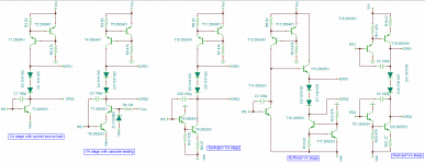
I'm sorry in the push-pull VA stage I forgot to put the Miller compensation capacitors.
Corrected picture attached,
Best regards,
Daniel Almeida

In my simulation with SPICE I usually begin with no.1
Then if I want lower THD I go for no.3 - the darlington VAS.
Darloington VAS increases gain which makes more FeedBack.
Then there is combination of a CCS and a bootstrap.
http://www.diyaudio.com/forums/solid-state/186981-bootstrapsccs-t-tmc.html
http://www.diyaudio.com/forums/solid-state/186981-bootstrapsccs-t-tmc.html
I like the common gate J-fet amplifier or better yet, push pull common gate. For higher voltage circuits I have used small signal mosfets as common gate VAS as well. I suppose it is remenisent of the common grid triode circuit.🙂
Last edited:
mosfet have poor gm C ratio compared to bjt - JLH suggested using the mosfet for the "infinite beta" DC gain but cascoding with bjt for reduced parasitic output C
http://www.diyaudio.com/forums/solid-state/70279-current-mirrors-driving-fets-2.html#post798468 for LTspice source
with degeneration it is possible to somewhat compensate the VAS base current with the ("feedbacK"?) current mirror
I showed this combination of the JLH mosfet VAS idea and a "balanced" current mirror: (G1,2, I2,3 are a abstract spice model of diff pair)
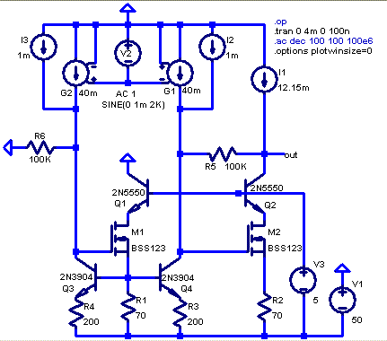
M1,2 equally load both sides of the mirror, R1,2 give equal operating point (still need to coordinate VAS, diff pair CCS to have equal currents in M1,2)
bjt VAS could be done the same - to the degree you can rely on hfe match
even without cascoding - connect the servo Q collector to the amp output and it will have very nearly the same operating point as the VAS Q - maintaining matching over AC operation too
unless monolithic input pair are used I doubt the current density/Shockley Ic/Vbe relation will match to better than 1% when trimmed for 0 V offset, 1% Ic imbalance ~= 0.25 mV input offset
http://www.diyaudio.com/forums/solid-state/70279-current-mirrors-driving-fets-2.html#post798468 for LTspice source
Last edited:
- Status
- Not open for further replies.
- Home
- Amplifiers
- Solid State
- VA topologies for audio amplifiers