Hello all. This is my first official post outside the lobby forum. I currently have a Voice of Music 8810 amplifier. It works as is, but, I have bought some parts to upgrade it.
I was interested in adding a fuse and three prong cord. Now, from what I understand this seems to be straight forward on how to connect it. My question on this, is it a stupid idea to wire a three prong plug without the addition of the fuse?
Also, I have read that these older amps are polarity sensitive? I read a couple stories where in some cases the plug inserted into the wall backwards would produce electricity to the chassis and cause a shock or introduce an undesirable hum. I plugged mine in both ways, no shock, and really no hum at all even when cranked up all the way. I literally have to put my ear down by the cab to even hear any hum.
The amp for the last couple days has been experiencing some slight cracking popping noises which prompted me to buy some new tubes capacitor and coupling caps. The noise kinda reminds me of cassette tape flutter and hiss noise. Best way for me to describe it. Does this most likely sound like a tube issue?
Now, when I swap out the parts when I get them, should the amp be restarted with a variac? (I don't have one.) Or is it ok to just turn it on after new component installation since it was already in operating condition beforehand.?
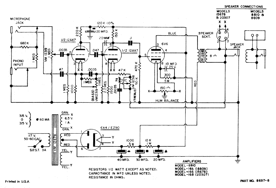
My main concern however is making it safe via grounding and a fuse. My other concern is not knowing if this amp uses "death caps". I have included the schematic for seasoned eyes to look at. I really appreciate your taking the time to read and offer your insights.
I was interested in adding a fuse and three prong cord. Now, from what I understand this seems to be straight forward on how to connect it. My question on this, is it a stupid idea to wire a three prong plug without the addition of the fuse?
Also, I have read that these older amps are polarity sensitive? I read a couple stories where in some cases the plug inserted into the wall backwards would produce electricity to the chassis and cause a shock or introduce an undesirable hum. I plugged mine in both ways, no shock, and really no hum at all even when cranked up all the way. I literally have to put my ear down by the cab to even hear any hum.
The amp for the last couple days has been experiencing some slight cracking popping noises which prompted me to buy some new tubes capacitor and coupling caps. The noise kinda reminds me of cassette tape flutter and hiss noise. Best way for me to describe it. Does this most likely sound like a tube issue?
Now, when I swap out the parts when I get them, should the amp be restarted with a variac? (I don't have one.) Or is it ok to just turn it on after new component installation since it was already in operating condition beforehand.?
My main concern however is making it safe via grounding and a fuse. My other concern is not knowing if this amp uses "death caps". I have included the schematic for seasoned eyes to look at. I really appreciate your taking the time to read and offer your insights.
Your circuit shows that the unit has a mains transformer which means that the chassis is always isolated from the mains irrespective of mains lead polarity.
There should be no issues in grounding the chassis via a correctly wired 3 core lead as exactly the same scenario could occur via grounding of the inputs (a legitimate connection mode).
You could introduce a ground loop (hum) doing this but the only way to know would be to try it in your intended application.
Safety requirements are more stringent today. A fused plug feeding a 3 core lead is really there to protect the cable, the unit itself also being fused internally with a more appropriate value (which seems not to be the case here).
As long as you fit the new parts correctly, and they are of the correct values and correctly polarised (where needed) then you can just switch straight on.
Hello and thanks for the reply.
Please forgive my ignorance, but when you state...
"Your circuit shows that the unit has a mains transformer which means that the chassis is always isolated from the mains irrespective of mains lead polarity."
Does this basically mean if something was to fail that there is no way for electricity to leak to the chassis? Is this thing safe as is? Sorry for the menial questions. I just want to be able to use this thing safely. Again thanks to all.
They are good questions 🙂 and if you are unsure then always ask.
So the transformer provides total isolation, but to go on from there and ask whether it provides total safety requires clarifying.
It should (the transformer) be designed in such as way that no conceivable failure mode within the transformer can allow any physical connection to occur between the transformer primary winding and the transformer frame (and hence on to the chassis).
It is as safe as it could be for a product of that era but I wouldn't like to say if the transformer would meet current requirements, or whether the unit as a whole would meet what we now call 'double insulated' standard which is applicable to products with a two core lead.
For example... could a wire become detached from say the mains switch and however remote the possibility, contact something within the unit. That would be a fail because the chassis could then become live. A three core lead would guard against that and blow the fuse (which is not present on the diagram 😉)
So it is as safe as it was designed to be but not be up to modern standards.
Cool! Now, for this particular amp, is it feasible to ground to one of the bolts on the power transformer and call it a day? This is great. I appreciate everything!
The safety concern you bring up about AC plug orientation applies to the old 5 tube radios that had no power transformer and one wire on the AC plug would land on the chassis! (You'll notice that these old radios don't have metal knobs)
On your amp, there should be a pair of black wires that come from the transformer and connect to the power cord/power switch. The fuse should ideally go on the line (non-transformer) side of the power switch, and the black (hot) wire of the 3 wire power cord should land on the other side of the fuse block.
The white power cord wire just hooks up to the second power transformer primary wire.
The green (ground) power cord wire needs a nice, solid connection to the chassis that's as close as is convenient to where the power cord enters the amp. Often times there's a terminal strip with an empty chassis lug nearby, or you can get a solder tab or ring terminal and solder the ground wire to that, then bolt it onto the chassis.
Much appreciated indeed! When I attach the ground bolt should I sand back some of the finish to bare metal? Or will it suffice as is?
Another thing if I may. I was reviewing the schematic and something caught my attention. I have a can capacitor in the amp. It's rated 450v-40uf, 150v-30uf, 450v-10uf, 450v-10uf. If you look at the schematic it shows a 40uf, 30uf, and a 20uf. Why is this? Thanks again for your time and patience.
Another thing if I may. I was reviewing the schematic and something caught my attention. I have a can capacitor in the amp. It's rated 450v-40uf, 150v-30uf, 450v-10uf, 450v-10uf. If you look at the schematic it shows a 40uf, 30uf, and a 20uf. Why is this? Thanks again for your time and patience.
In order for the ground to work it well, it needs to have as little resistance as possible. Anything that adds resistance. like rust, crud, varnish, rosin flux, may inhibit the performance of your amp.
The 2 10uf when paralleled makes the 20uf cap. They probably did not have the right value of the can cap they needed so they just added another cap to give the correct value. Or someone may have changed out the can cap previously and he did not have the correct value and just used it anyway.
The 2 10uf when paralleled makes the 20uf cap. They probably did not have the right value of the can cap they needed so they just added another cap to give the correct value. Or someone may have changed out the can cap previously and he did not have the correct value and just used it anyway.
Last edited:
> stupid idea to wire a three prong plug without the addition of the fuse?
Two different issues. You "can" do either/or/both.
First: you should *always* replace 60 year old power cords unless you are totally satisfied as to their integrity. Most are sad rot, and will bite you. The few cases that are not rot, these days you almost CERTAINLY want to replace 2-wire with 3-wire to get the benefit of "ground". While you could pull the cord off a 1957 power saw, I will assume you will get a fresh one.
You should ALWAYS connect all touchable metal to the electric supply "ground". This is a 3-pin plug and a good solid clean connection to chassis.
With a fresh power cord (2-wire or 3-wire), the fuse is *perhaps* optional. We run lamps without internal fuses! A fair number of other things too. Small lamp-cord in the US is accepted without fusing because it will spark and bubble and smolder but "usually" will not set the carpet on fire before it burns-through. Fat cords reliably blow the 20A fuse in the cellar.
However in all DIY, including DIY repair/mod of commercial gear, mistakes happen. One-off work has more chance of scorching the carpet or leaving the family in the dark, compared to approved mass-produced gear (if they get it right once, they probably get it right 99 out of 100). So an internal fuse is Good Practice.
> not knowing if this amp uses "death caps". I have included the schematic ...
The answer is obvious to an experienced tech. If it is not clear to you, I really think you should get local experienced oversight, because there's other places where limited understanding can lead to real trouble.
> stupid idea to wire a three prong plug without the addition of the fuse?
Two different issues. You "can" do either/or/both.
First: you should *always* replace 60 year old power cords unless you are totally satisfied as to their integrity. Most are sad rot, and will bite you. The few cases that are not rot, these days you almost CERTAINLY want to replace 2-wire with 3-wire to get the benefit of "ground". While you could pull the cord off a 1957 power saw, I will assume you will get a fresh one.
You should ALWAYS connect all touchable metal to the electric supply "ground". This is a 3-pin plug and a good solid clean connection to chassis.
With a fresh power cord (2-wire or 3-wire), the fuse is *perhaps* optional. We run lamps without internal fuses! A fair number of other things too. Small lamp-cord in the US is accepted without fusing because it will spark and bubble and smolder but "usually" will not set the carpet on fire before it burns-through. Fat cords reliably blow the 20A fuse in the cellar.
However in all DIY, including DIY repair/mod of commercial gear, mistakes happen. One-off work has more chance of scorching the carpet or leaving the family in the dark, compared to approved mass-produced gear (if they get it right once, they probably get it right 99 out of 100). So an internal fuse is Good Practice.
> not knowing if this amp uses "death caps". I have included the schematic ...
The answer is obvious to an experienced tech. If it is not clear to you, I really think you should get local experienced oversight, because there's other places where limited understanding can lead to real trouble.
Thanks for taking your time to respond. The amp I have is actually in not too bad of shape, aesthetically. The power cord is good, I would say. (I have included a pic of the amp).
I also appreciate the concern. Unfortunately, where I'm located there is no way to get "local experienced oversight". I am comfortable with electronics and I do have a basic comprehension of it. The thing is, I have never worked on anything that is high voltage, or, any amp for that matter which is why all the questions. I'm really not interested in cooking myself. However, I'm interested in learning how to bring this up a bit.


Ok, so I have been educating myself for the last week or so. I have learned how to safely discharge the capacitors (which was my biggest concern) and have consulted an electrician where I work who has agreed to look over he amp after I finish it!
With that said. I have started the re-work of it. I have so swapped out a few capacitors. Easy enough. The one thing that is driving me semi-crazy though is the figuring of wiring the 3 prong cord.
In the above post by audiowize, it says I should have two black wires running from the transformer. I can see those. One runs to the power cord, the other to the power switch. However, i'm kind of lost as to how I should proceed to connect the white wire. In the above post it says to just connect the white wire to the second transformer primary lead. How can I determine what lead that is? Also, as of now the white whire from the power cord is connected to the other side of the switch. Should the white wire from the power cord be ran here? Thanks for offering your insight.
 Moved to the instrument & amps forum since it is a musical instrument amplifier.
Its very important you get this correct but without having seen the original set up of wires I'm not going to say you connect 'this colour here' and 'that colour there'.
Your circuit diagram shows the classic two core lead connecting to the primary. It is good practice to wire the switch to the 'live' side of the incoming supply although not doing so will not affect the basic operation. But it is good practice and should always be done.
I assume the white wire is now the extra core in the 3 core mains lead and is 'ground'.
Is that correct ?
If so then that wire should connect to the chassis to achieve the grounding you wanted. The chassis should also be the same point electrically as that proper earth symbol on the diagram. We always connect main ground wires to a substantial chassis point in practice such that it could if needed handle the full fault current.
In the UK we would see Brown, Blue and a Green/Yellow as the three cores making up a lead. This is how they connect.
Edit... I'm looking at USA mains plugs and see that Black is live, White is neutral and Green is earth. So using my diagram above you should be able to figure out which colour to use to go where.
Attachments

White is neutral, that goes directly to one side of the transformer primary, black is line and should go first to a fuse, and then to the switch and finally the other side of the transformer primary. (If you use a bulkhead fuse holder the line connection goes to the floating terminal at the end furthest from the chassis wall so that if the fuse is removed with mains connected there is no shock hazard) Something like a 0.75 - 1A MDL fuse should be adequate.
The green/yellow stripe (or solid green) conductor should be crimped to a ring terminal and bolted directly to the chassis (bolt not used to secure anything else) with either a star washer or keps nut to assure it does not back off.
The green/yellow stripe (or solid green) conductor should be crimped to a ring terminal and bolted directly to the chassis (bolt not used to secure anything else) with either a star washer or keps nut to assure it does not back off.
Thanks for reading. It's very much appreciated. I still have some reservations about this so I decided to include a couple of pics to maybe see if that helps a bit more.
Pic 1 shows the power cable coming into the amp. The white wire is connected, and a black wire from the PT is connected to the other side of the switch.

Pic 2 shows illustrates the black wire from the power cord connected to a terminal with another black wire form the PT connected to it. Is this where the fuse should be inserted? Between these two points here in pic 2?

Pic 3 is what I believe is the ground. This is a yellow wire with green stripes on it connected to the cap can. Is this the ground as of now? So all I would basically do here is attach the ground from the cord to the chassis?

Thanks again for looking and taking your time to help. Your patience is greatly appreciated.
Pic 1 shows the power cable coming into the amp. The white wire is connected, and a black wire from the PT is connected to the other side of the switch.
Pic 2 shows illustrates the black wire from the power cord connected to a terminal with another black wire form the PT connected to it. Is this where the fuse should be inserted? Between these two points here in pic 2?
Pic 3 is what I believe is the ground. This is a yellow wire with green stripes on it connected to the cap can. Is this the ground as of now? So all I would basically do here is attach the ground from the cord to the chassis?
Thanks again for looking and taking your time to help. Your patience is greatly appreciated.
Working from pictures is never easy 🙂
So picture #1 does appear to show white (neutral) as going directly to the switch. That isn't good practice... we always switch the live side if just using a single pole switch as here. The reason why is that when the switch is off, the transformer primary is 'dead' with no voltage on it. It doesn't effect the operation of the set but it affects you if you unwittingly touch the primary connections while thinking it is off.
So what you want is the black of the mains lead going to your new and to be added fuse holder, and from the fuse holder to the switch.
The existing black wire from switch to transformer remains as is.
The new white lead of the new mains cable goes to the existing terminal board you show in picture #2 which you say is the other wire from the transformer.
The green earth wire connects to any sound metal point on the chassis. Picture #1 has a possible ready drilled hole next to the incoming mains lead. Scrape any paint from the chassis to ensure a good connection.
Also post #1 seems to show the existing black lead going through a 'rough' hole in the chassis. That is not safe if so. The hole should have a grommet to prevent the metal cutting the insulation.
So in a nutshell, I'm just flipping the cable around? Another thing if I may. The switch. How can I access this cover on it? Do I just gently pry underneath it? This has been of great help.
Without disagreeing with Mooly, I would paint the white wire black (mentally) and treat it as "second live wire". Specifically I would NOT bother to move fuse or switch to one color or another.
White and Black DO have specific meaning for in-wall wiring (North American conventions). Do NOT get it wrong when wiring a house!!
But the outlet, and the plug, and ignorant workers, make this uncertain in the cord and appliance (amplifier). In my last kitchen, 60% of outlets had white/black reversed. This may also be common when you play cheap dives with cheap owners and "legacy" or idiot-rigged wiring.
> when the switch is off, the transformer primary is 'dead' ... if you unwittingly touch the primary connections while thinking it is off.
I'll argue that with *cord and plug* appliances, you *ALWAYS UN-PLUG* before sticking your fingers inside!! Don't trust the white/black, don't trust a switch, never trust a fuse. Don't even trust the plug until you run your hand up the cord and verify it IS the thing you thought. Keep the cord bunched-up and the plug in sight. Yes, sometimes you "must work live". Remember that 120V-400V can be as deadly as a rattle-snake, but faster, and invisible.
Without disagreeing with Mooly, I would paint the white wire black (mentally) and treat it as "second live wire". Specifically I would NOT bother to move fuse or switch to one color or another.
.
So you're saying basically leave it as is when connecting the new cable???
On new stuff, do what Mooley says.
But never trust White/Black!!
On vintage stuff, do minimal mods. Fuse is good. Fretting the line-cord black/white is IMHO false security. Electricity is color-blind, and so are many of the people who wire houses and line cords. ALWAYS assume the snakes are ready to bite.
But never trust White/Black!!
On vintage stuff, do minimal mods. Fuse is good. Fretting the line-cord black/white is IMHO false security. Electricity is color-blind, and so are many of the people who wire houses and line cords. ALWAYS assume the snakes are ready to bite.
Attachments

- Status
- Not open for further replies.
- Home
- Live Sound
- Instruments and Amps
- V-M 8810 Rebuild. Safety Reassurance.