
LMAO@MrJohn you wrote:
"I got some good soldering practice as a child with R/C cars and most recently building 2 ACAs... but de-soldering components on a pc board, not so much."
In this case, my advice: don't (de-)solder yourself in this precious amplifier 😎
Amen!One of the worlds best audio workshops is not far from you: passlabs.com
@MrJohn, I am sure you already "heard" my advice but I will share it here for posterity in case anyone else is experiencing similar issues with the B2 and is in search of answers:Well i did some cleaning of the contacts and the heads of the fuses and shot some deoxit in the speaker gain pots, not that i was hearing anything scratchy when i used them. From what i have seen on some restoration videos, signal does goes through them, so i figured, why not?
I'm testing for the distortion with the speaker gain turned up 100% on Channel A. So far so good! I might have to hook this up to my main speakers to test some more.
I noticed one of my vu meter lights are out. If i were to replace it, do i need to desolder this thing? The bulb doesn't just pop out? The pictures shows both inside ones being out, but the right side came on after a few minutes.
B2 is a fantastic sounding amplifier when working properly but it is about 45 years old by now. My suspicion is that when designed and built new, while the Yamaha engineers were busy working with Mr. Nishizawa to bring vfets to the audio world, the Yamaha marketing department was working on adding selectors and switches to make the amp look like an integrated amp as much as possible, likely to attract some more customers (speculating here). Nonetheless, why Yamaha decided to add those pots and switches there is less relevant. What is relevant is that they are a point of failure and a source of grief for any B-2 owner.
Cleaning the switches of the B2 is fixing a symptom temporarily. Yes, the switches are open air switches and that means there is access to clean them if taken apart. It also means that unwanted elements can creep back in soon enough there after. The resistance of those contacts AFTER cleaning them with Deoxit s still anywhere from one or two ohms to 50 ohms or even more, looking otherwise all clean.
An additional issue is that within the same selector switch, Yamaha decided to handle, both VDC and signal switching. When things start to get dirty inside there, DC bleeding in the signal path starts to happen.
Note: Using any type of abrasive materials on cleaning silver plated contacts will absolutely damage them permanently.
What I found to be the real fix for this problem is sealed relays as replacements and a circuit redesign.
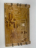
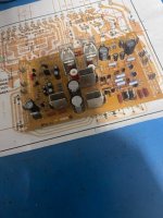
Additional to the front panel pots and switches, another issue with the B2 is the way the power supply was mechanically designed. In the way the B2 PSU was conceived, it creates more or less an oven like space where the heat is trapped and the internal components get slowly baked. This is primarily noticeable with B2 units that spent their time inside closed spaces. What exacerbates the problem further is that Yamaha just as other manufacturers of the period, used the dreaded Sony glue to mechanically attach the TO-220 regulator transistors to the board and some of the capacitors. These transistors rest upside down so the heatsinks in almost all cased part away from the PCB. Also, overtime the glue becomes corrosive and inductive which introduces other issues. INHO, working with the old PCB is doable and I have rebuilt more than two dozen B2 PSU PCBs by now, but the way to alleviate the core of these issues is a new PSU FR4 PCB that does not sag, with a design that adds ventilation for each of the components that scorch the board and good mechanical attachment for the TO-220 heatsinks.
Otherwise, the amp is very robust as far as circuit design and this is one reason why the Yamaha B-2 has the highest survivability rate out of all JP vfet units from the 70s.
And since this is DIY audio, why all the talk without some visuals:
Note that the fuse holders can be substituted with pigtail fuses.
I I've watched all your videos a couple times already. I knew about your gain board thing, but I didn't know you were printing new boards now! Very nice!@MrJohn, I am sure you already "heard" my advice but I will share it here for posterity in case anyone else is experiencing similar issues with the B2 and is in search of answers:
View attachment 1107708View attachment 1107709
@MrJohn, I am sure you already "heard" my advice but I will share it here for posterity in case anyone else is experiencing similar issues with the B2 and is in search of answers:
B2 is a fantastic sounding amplifier when working properly but it is about 45 years old by now. My suspicion is that when designed and built new, while the Yamaha engineers were busy working with Mr. Nishizawa to bring vfets to the audio world, the Yamaha marketing department was working on adding selectors and switches to make the amp look like an integrated amp as much as possible, likely to attract some more customers (speculating here). Nonetheless, why Yamaha decided to add those pots and switches there is less relevant. What is relevant is that they are a point of failure and a source of grief for any B-2 owner.
Cleaning the switches of the B2 is fixing a symptom temporarily. Yes, the switches are open air switches and that means there is access to clean them if taken apart. It also means that unwanted elements can creep back in soon enough there after. The resistance of those contacts AFTER cleaning them with Deoxit s still anywhere from one or two ohms to 50 ohms or even more, looking otherwise all clean.
An additional issue is that within the same selector switch, Yamaha decided to handle, both VDC and signal switching. When things start to get dirty inside there, DC bleeding in the signal path starts to happen.
Note: Using any type of abrasive materials on cleaning silver plated contacts will absolutely damage them permanently.
What I found to be the real fix for this problem is sealed relays as replacements and a circuit redesign.
Additional to the front panel pots and switches, another issue with the B2 is the way the power supply was mechanically designed. In the way the B2 PSU was conceived, it creates more or less an oven like space where the heat is trapped and the internal components get slowly baked. This is primarily noticeable with B2 units that spent their time inside closed spaces. What exacerbates the problem further is that Yamaha just as other manufacturers of the period, used the dreaded Sony glue to mechanically attach the TO-220 regulator transistors to the board and some of the capacitors. These transistors rest upside down so the heatsinks in almost all cased part away from the PCB. Also, overtime the glue becomes corrosive and inductive which introduces other issues. INHO, working with the old PCB is doable and I have rebuilt more than two dozen B2 PSU PCBs by now, but the way to alleviate the core of these issues is a new PSU FR4 PCB that does not sag, with a design that adds ventilation for each of the components that scorch the board and good mechanical attachment for the TO-220 heatsinks.
Otherwise, the amp is very robust as far as circuit design and this is one reason why the Yamaha B-2 has the highest survivability rate out of all JP vfet units from the 70s.
And since this is DIY audio, why all the talk without some visuals:
View attachment 1107708View attachment 1107709
Note that the fuse holders can be substituted with pigtail fuses.
that is nice work, labor of love

Hi@MrJohn, I am sure you already "heard" my advice but I will share it here for posterity in case anyone else is experiencing similar issues with the B2 and is in search of answers:
B2 is a fantastic sounding amplifier when working properly but it is about 45 years old by now. My suspicion is that when designed and built new, while the Yamaha engineers were busy working with Mr. Nishizawa to bring vfets to the audio world, the Yamaha marketing department was working on adding selectors and switches to make the amp look like an integrated amp as much as possible, likely to attract some more customers (speculating here). Nonetheless, why Yamaha decided to add those pots and switches there is less relevant. What is relevant is that they are a point of failure and a source of grief for any B-2 owner.
Cleaning the switches of the B2 is fixing a symptom temporarily. Yes, the switches are open air switches and that means there is access to clean them if taken apart. It also means that unwanted elements can creep back in soon enough there after. The resistance of those contacts AFTER cleaning them with Deoxit s still anywhere from one or two ohms to 50 ohms or even more, looking otherwise all clean.
An additional issue is that within the same selector switch, Yamaha decided to handle, both VDC and signal switching. When things start to get dirty inside there, DC bleeding in the signal path starts to happen.
Note: Using any type of abrasive materials on cleaning silver plated contacts will absolutely damage them permanently.
What I found to be the real fix for this problem is sealed relays as replacements and a circuit redesign.
Additional to the front panel pots and switches, another issue with the B2 is the way the power supply was mechanically designed. In the way the B2 PSU was conceived, it creates more or less an oven like space where the heat is trapped and the internal components get slowly baked. This is primarily noticeable with B2 units that spent their time inside closed spaces. What exacerbates the problem further is that Yamaha just as other manufacturers of the period, used the dreaded Sony glue to mechanically attach the TO-220 regulator transistors to the board and some of the capacitors. These transistors rest upside down so the heatsinks in almost all cased part away from the PCB. Also, overtime the glue becomes corrosive and inductive which introduces other issues. INHO, working with the old PCB is doable and I have rebuilt more than two dozen B2 PSU PCBs by now, but the way to alleviate the core of these issues is a new PSU FR4 PCB that does not sag, with a design that adds ventilation for each of the components that scorch the board and good mechanical attachment for the TO-220 heatsinks.
Otherwise, the amp is very robust as far as circuit design and this is one reason why the Yamaha B-2 has the highest survivability rate out of all JP vfet units from the 70s.
And since this is DIY audio, why all the talk without some visuals:
View attachment 1107708View attachment 1107709
Note that the fuse holders can be substituted with pigtail fuses.
is it possible to buy this PCB ? I have one B2 need service. This could be the best upgrade in my B2 as i have the old PCB with new Caps working.
kannan
yes, PM pleaseHi
is it possible to buy this PCB ? I have one B2 need service. This could be the best upgrade in my B2 as i have the old PCB with new Caps working.
kannan
- Home
- Amplifiers
- Pass Labs
- V-FET amplifier repair (Southern, California)