Hi Victor,
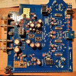
Is this the proper orientation for the V Cap capacitors on the TU-8600S board?
View attachment 863260
You told me on the phone that red was negative and green was positive. Do I strip those red and green insulators only to the point where the legs fit through the holes on the board, or do I remove them completely?
Thanks,
Allan
Last edited:
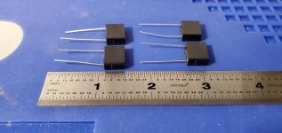
CuTF & TFTF Series
The green lead indicates the outermost foil, and should be connected to the lowest impedance path to ground. Another way to identify outer foil is the writing on the label flows towards the outer foil.
Use a quality wire stripper when removing the insulation, like a Klein No. 11055
When used in amplifiers, outer foil should be connected towards the plate of first stage
If using as a bypass cap to ground, connect green lead to ground.
If using as a bypass cap from a signal to B+, connect green lead to B+.
If using in a feedback position, connect green lead towards the output
When securing near objects or circuit traces that have sharp edges, Silicone tape can work well as a buffer, to prevent laceration of the V-Cap's outer skin.
ODAM- installation note
The short lead indicates the outermost foil, and should be connected to the lowest impedance path to ground. Another way to identify outer foil is the writing on the label flows towards the outer foil.
The ODAM and OIMP series capacitors have metal bodies that are electrically conductive. Ensure that the body doesn't make electrical contact with any other portion of the circuit other components or electrically LIVE circuit traces. Heatshrink, 3M foam tape, or silicone tape around the body may be used to help insulate, and protect from electrical short.

Hi,
Looks like Victor posted a short video with the same orientation. Thanks!
ELEkit TU-8600S with vcap copper on Vimeo
Looks like Victor posted a short video with the same orientation. Thanks!
ELEkit TU-8600S with vcap copper on Vimeo
Last edited:
Just out of curiosity, aren't these caps backwards?
The outer foil (green wire) is the outer shield, and should be connected to the lower impedance path to ground. In this case the plates of V1, V2, and V3 are the lower impedance paths to ground, while the grids of V2, V3, V4, and V5 are the high impedance side, and should be connected to the inner (shielded) electrode of the capacitors.
I don't have these capacitors but may consider getting them after I have a chance to listen to the stock ones.
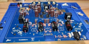
FYI
Here is a photo of the stock caps.
View attachment 898514
Victor, to help others who may be as confused as I was with the manufacturer's instructions regarding orientation, could you verify that the orientation of the V caps in my previous photo is the recommended orientation?
Here is a photo of the stock caps.
View attachment 898514
Victor, to help others who may be as confused as I was with the manufacturer's instructions regarding orientation, could you verify that the orientation of the V caps in my previous photo is the recommended orientation?