Building a bass pre-amp for use with a class D power amp module. The documentation for the power amp says the balanced input cannot exceed 12 volts on the +/- inputs and my pre-amp works on 15 volt rails so I think I need to clamp the outputs to 12 volts, just to avoid any spikes. I want to push the power amp as much as possible.
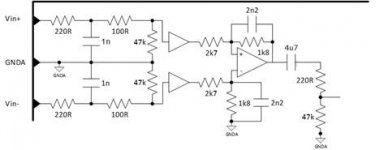
The first attachment is the input section of the class D power amp from the documentation.
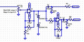
The second attachment is the output of my pre-amp with a clamp using paired 10v zener diodes to ground.
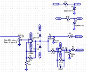
The third attachment is another clamp with silicon diodes going to 12 volt rails generated from the 15 volt rails using 10v zener diodes.
In both of these I have forgotten to add a resistor right before the clamping diodes. Probably something really small, under 1k.
Now which method is better, in terms of distortion, impedance or any other problems?
Is there a better way that doesn't involve many more components?
Can I lose the output caps or at least not use bi-polars?
Anything else wrong with this?
I'm using 10v zener diodes and not 12v zeners because in LTSpice simulations the flattened peaks were always a little above the specified voltage, because of the soft-knee characteristics of zener diodes.
The first attachment is the input section of the class D power amp from the documentation.
The second attachment is the output of my pre-amp with a clamp using paired 10v zener diodes to ground.
The third attachment is another clamp with silicon diodes going to 12 volt rails generated from the 15 volt rails using 10v zener diodes.
In both of these I have forgotten to add a resistor right before the clamping diodes. Probably something really small, under 1k.
Now which method is better, in terms of distortion, impedance or any other problems?
Is there a better way that doesn't involve many more components?
Can I lose the output caps or at least not use bi-polars?
Anything else wrong with this?
I'm using 10v zener diodes and not 12v zeners because in LTSpice simulations the flattened peaks were always a little above the specified voltage, because of the soft-knee characteristics of zener diodes.
Attachments
Easy one first. With circuit as it stands you can lose the output caps and 220k's but you need to use a FET opamp to eliminate DC offset issues. The pot connected directly to the opamp input is not a good idea, in fact its a no no. AC couple the wiper and use a 0.47uf film cap and 330k or 470k resistor to ground to bias the opamp. Its quieter and much safer. Think what happens to the opamp bias if the wiper momentarily loses contact. Also passing any current through the wiper (conventional bjt opamp) would create noise as the pot was turned.
Protection... the two series zeners might have an advantage but I would use each zener plus a series 1N4148 rather than just having the two zeners in parallel. With a low value driving resistor there should be no distortion issues.
Protection... the two series zeners might have an advantage but I would use each zener plus a series 1N4148 rather than just having the two zeners in parallel. With a low value driving resistor there should be no distortion issues.
Hi,
Far too over complicated. Just add an attenuator to the power
amplifier input, say 4.7K in series and 10K in parallel and that
should guarantee the power amplifier never sees > 12V.
rgds, sreten.
Far too over complicated. Just add an attenuator to the power
amplifier input, say 4.7K in series and 10K in parallel and that
should guarantee the power amplifier never sees > 12V.
rgds, sreten.
Most audio op-amps cannot swing rail to rail so this is somewhat less of an issue than it seems, however throwing away 3dB of gain/headroom seems somewhat pointless to me. (Attenuator on input of amp suggested previously)
I would be inclined to place the protection at the input of the amplifier (Unless for some reason you can't)
I've used series connected back to back diodes in pro-audio applications without a problem. A small series resistance between them and the op-amp is all that is required.
Note though that zeners have a tolerance and the zener voltage may also depend to a small extent on the current through the zener. You might want to select a lower voltage zener as a result or measure them. The zeners only need a voltage rating sufficient not to ever turn on at the audio voltage required for full output.
Another gambit that works well with op-amps is to reduce the supply voltage just enough so that their pk swing (due to internal losses) cannot exceed the maximum safe value at the PA input. (Possibly 13-14V supply rails)
You should not design stuff, if you are heated. At 37°C i mean: The power amp is is likely to have flat maximum power. Look up or measure maximum input voltage before clipping. Then clamp input to a bit above that. For example, if full-scale input is 1 VoltRMS, then two red LEDs will do.I want to push the power amp as much as possible.
however throwing away 3dB of gain/headroom seems somewhat
pointless to me. (Attenuator on input of amp suggested previously)
Hi,
Said headroom simply doesn't exist and 3dB loss is peanuts.
For sure the power amplifier will clip with an input level way
below the the maximum input voltages being discussed.
What is being discussed in damaging, not normal levels.
rgds, sreten.
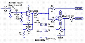
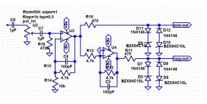
Thanks Mooly, that's exactly the info I wanted. I though I could get away with connecting the pot directly to the op-amp because it follows a 1uF film cap but it's changed now. Attached is the new version with 1N4148 silicon diodes in series with 10v zener diodes for protection. It seems work exactly as I want in LTSpice. (Great LTSpice tutorials by the way)
sreten, for clarification I'm not looking for attenuation. This is the output of a bass pre-amp which is directly connected to a class D power module with an input section shown in the first post's attachments. The pot on the pre-amp is the master volume. I want to have the capability of driving the power amp module to close to full power even if it will probably never happen in real life and I just want some protection against voltage spikes past the 12 volt limit for the power amp inputs.
sreten, for clarification I'm not looking for attenuation. This is the output of a bass pre-amp which is directly connected to a class D power module with an input section shown in the first post's attachments. The pot on the pre-amp is the master volume. I want to have the capability of driving the power amp module to close to full power even if it will probably never happen in real life and I just want some protection against voltage spikes past the 12 volt limit for the power amp inputs.
Attachments
That looks OK  and pleased to hear your finding the LT stuff useful.
Just one observation, the output impedances are very unequal which in practice is probably a non issue for a bass orientated design and assuming the input impedance of the power amp is high.
To make them equal would need a third opamp as a buffer for the top output feed.
and pleased to hear your finding the LT stuff useful.Just one observation, the output impedances are very unequal which in practice is probably a non issue for a bass orientated design and assuming the input impedance of the power amp is high.
To make them equal would need a third opamp as a buffer for the top output feed.
I was thinking about the impedance with this set up and I think I will have two sets of diodes, one on each output.
The clamping diode has nothing to do with +/-9V power suppy....
Sajti
I was thinking about the impedance with this set up and I think I will have two sets of diodes, one on each output.
That's one solution and workable.
The clamping diode has nothing to do with +/-9V power suppy....
Sajti
True 🙂
Why don't thou just look up or measure input voltage needed for full-scale power output and clamp input voltage to a bit higher than that? It is prolly around 1Vrms, which is +-1.4V, so two red LEDs clamping to +-2V will do.I want to have the capability of driving the power amp module to close to full power even if it will probably never happen in real life and I just want some protection against voltage spikes past the 12 volt limit for the power amp inputs.
- Status
- Not open for further replies.
- Home
- Amplifiers
- Solid State
- using zener diodes to clamp voltage?