I'm considering using solid state DC relays to implement a "fast turn off" of the rails from a linear power supply feeding an amplifier. The idea is that I want to immediately kill the rails to the amp and then let the PS caps slowly drain over 30 sec or so through a bleed resistor.
I found a thread from 2010 on this topic, but the application was not for a power amp:
http://www.diyaudio.com/forums/power-supplies/176521-solid-state-relays.html
See especially post #9.
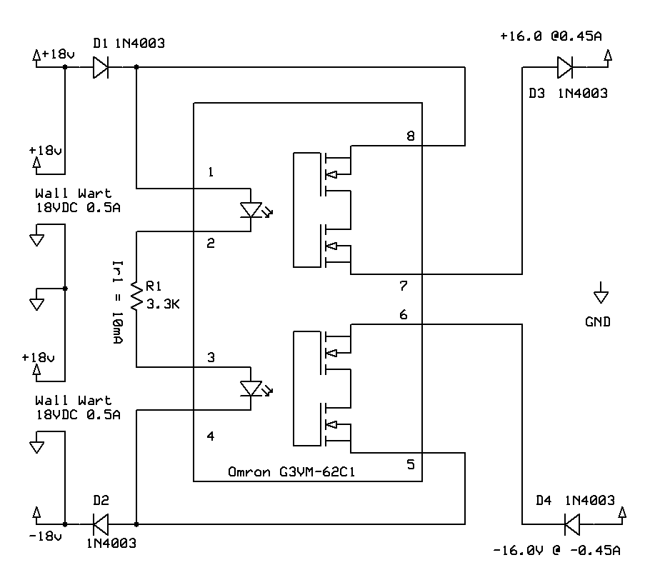
I can think of at least one application where this would be of benefit: the PS for a TDA7293 based chip amp. For the 7293 if the negative rail is accidentally disconnected (fuse blows etc) but the positive rail remains active the IC will explode. The scheme shown below from the 2010 thread would make for a simple mutual shutdown circuit, and the branch feeding the inputs (labeled 1-2-3-4) to the SSRs could also be relay controlled so that you could remotely shut off the PS rails on command.
Any drawbacks for using SSRs in this application? Will the leakage current of the SSR be a problem? I am considering some cheap SSRs from China that are available through Ebay at about $10-$15 each, rated 60Vdc and 40A.
I found a thread from 2010 on this topic, but the application was not for a power amp:
http://www.diyaudio.com/forums/power-supplies/176521-solid-state-relays.html
See especially post #9.
I can think of at least one application where this would be of benefit: the PS for a TDA7293 based chip amp. For the 7293 if the negative rail is accidentally disconnected (fuse blows etc) but the positive rail remains active the IC will explode. The scheme shown below from the 2010 thread would make for a simple mutual shutdown circuit, and the branch feeding the inputs (labeled 1-2-3-4) to the SSRs could also be relay controlled so that you could remotely shut off the PS rails on command.
Any drawbacks for using SSRs in this application? Will the leakage current of the SSR be a problem? I am considering some cheap SSRs from China that are available through Ebay at about $10-$15 each, rated 60Vdc and 40A.
Member
Joined 2009
Paid Member
A very timely thread. I have a 3 channel amplifier with a linear power supply. I have no dc speaker protection installed. Instead of the usual relay on the outputs of each channel I'm considering a system to disconnect the power rails after the main power supply filter capacitors.
I've designed and built speaker disconnect systems using SS relays before and like this approach. I used the TLP190B photovoltaic chip to drive the gates of a pair of back-to-back NMOS devices. For my thoughts on a dc speaker protection option of cutting the rails I need a simple latch so that once the rails are cut the loss of a dc error signal from the output will not result in the rails coming back up again until mains power is cycled.
I would feel safest with a DIY discrete SS relay, rather than a module from eBay with unknown pedigree. A pair of NMOS and a TLP190B should be available at reasonable prices. I may parallel up NMOS devices for improved robustness at high currents since I'm looking at a potential dc-fault in an amplifier that might signify significant current flow into the load.
I shall be interested to see what you come up with.
I use relays all the over 100 watt amplifiers that I build. These are installed on both sides of the ac mains input and also on the plus channel output to the speakers.
Open relays with a removable cover seem a good idea to me so that I can check the relay if a problem occurs. Your price seems high as the last ones I bought from Mouser were £2.15 each and £0.60 for the cover. Mouser part no 655-t90n1d12-24. A Potter and Brumfield T90 series 30A pcb relay.
Some have been in use for over 20 years and still work fine. They also look and measure ok when checked. I have never had a burned contact except for a mistake when an output was shorted one time.
Don
I could tweak an existing cap multiplier/regulator project so that I can switch the gate of the output transistors off when I want to shut down. I have been mulling over that option as well, although I had originally intended to have another pair of caps AFTER the cap multiplier board...
What are the potential problems with the SSRs in this case? I'm not super familiar with all the flavors of SSR internals. Are some not really suitable for this application?
What are the potential problems with the SSRs in this case? I'm not super familiar with all the flavors of SSR internals. Are some not really suitable for this application?
I use relays all the over 100 watt amplifiers that I build. These are installed on both sides of the ac mains input and also on the plus channel output to the speakers.
Open relays with a removable cover seem a good idea to me so that I can check the relay if a problem occurs. Your price seems high as the last ones I bought from Mouser were £2.15 each and £0.60 for the cover. Mouser part no 655-t90n1d12-24. A Potter and Brumfield T90 series 30A pcb relay.
Some have been in use for over 20 years and still work fine. They also look and measure ok when checked. I have never had a burned contact except for a mistake when an output was shorted one time.
Don
Right, I wasn't really thinking speaker relay here...
But now that you mention it, have you ever measured the difference in distortion at the output with and without the speaker relay in the circuit? I know that Bob Cordell has written that some types induce distortion, but didn't provide any specifics. Just wondering how prevalent the distortion-increasing types are compared to the blameless ones (if those exist).
Member
Joined 2009
Paid Member
Bear in mind, you can make your own SS relay fairly easily from a pair of MOSFETs. There are no 'contact' issues to worry about.
There are lots of options, some of them have some good headroom on current handling: Digikey has the IRFSL4115PBF devices that are rated to 195A at 150V for $3.85ea if you buy 10 of them.
There are lots of options, some of them have some good headroom on current handling: Digikey has the IRFSL4115PBF devices that are rated to 195A at 150V for $3.85ea if you buy 10 of them.
But I can buy one of these that should do all of that:

$5-$10 depending on how many I buy and where I buy them...
I will be controlling the SSR using an Arduino or similar.
$5-$10 depending on how many I buy and where I buy them...
I will be controlling the SSR using an Arduino or similar.
Member
Joined 2009
Paid Member
I just searched for DC solid state relay on eBay. There are dozens of them out there at low prices. It does look more compelling than building one yourself, but I'm nervous about using something with no pedigree in a protection circuit. I also read somewhere else that these low cost SS relays are very slow - although the specifications published by the sellers looks just fine.
Remember the adage - if it looks too good to be true....
At these prices it's probably best just to buy a couple and try them out - not much to lose !
Remember the adage - if it looks too good to be true....
At these prices it's probably best just to buy a couple and try them out - not much to lose !
Last edited:
I just searched for DC solid state relay on eBay. There are dozens of them out there at low prices. It does look more compelling than building one yourself, but I'm nervous about using something with no pedigree in a protection circuit. I also read somewhere else that these low cost SS relays are very slow - although the specifications published by the sellers looks just fine.
Remember the adage - if it looks too good to be true....
At these prices it's probably best just to buy a couple and try them out - not much to lose !
It's not for protection. It's for shutdown/startup only. Some amp modules do some weird stuff as the PS caps slowly drain. I recently used a switching supply that is more like "instant off" and I rather like it! This got me thinking about how I can implement this kind of thing for a linear power supply without having to build something up from scratch.
I have read in a recently revived thread here about SSRs that the AC type often introduces a glitch into the AC waveform where it crosses 0V and this (as far as I can tell from the posts) may cause transformers to hum. Are there similar issues with a DC SSR? It seems like it would just be an on/off kind of device, perhaps suffering from some voltage drop and resulting power loss.
There exists a more simplistic approach: The crowbar.
A Thyristor is triggered on power down and discharges the caps within usec.
This is cheap, simple and effective.😉
A Thyristor is triggered on power down and discharges the caps within usec.
This is cheap, simple and effective.😉
and damages the capacitors.
It exceeds the dv/dt of the specification and should be reserved for an emergency to save/protect a more valuable component.
It exceeds the dv/dt of the specification and should be reserved for an emergency to save/protect a more valuable component.
Member
Joined 2009
Paid Member
Hi Andrew - has that been your experience ? I've never seen a crowbar in action but I have found capacitors to be very robust to occasional abuse on the bench top.
Manufacturers warn against rapid discharge specifically due to dv/dt limits.
Some film caps designed for high dv/dt can exceed 1000V/us. I can recall 1500V/us and 1800V/us but these are rare.
Many are decades below this.
Some film caps designed for high dv/dt can exceed 1000V/us. I can recall 1500V/us and 1800V/us but these are rare.
Many are decades below this.
If you'll be going the crowbar route, you also need a FUSE. i.e. once the crowbar activates, you're relying on that inline fuse to break.
Otherwise, if your'e only using a crowbar without a fuse, you'd have a permanent short circuit on the output of the power supply.
Otherwise, if your'e only using a crowbar without a fuse, you'd have a permanent short circuit on the output of the power supply.
There exists a more simplistic approach: The crowbar.
A Thyristor is triggered on power down and discharges the caps within usec.
This is cheap, simple and effective.😉
I'm not sure I want to dump 100,000uF of capacitance at 85Vdc like that... sounds a little scary...
A crowbar is meant for absolutely protecting the (presumed: very expensive) load from overvoltage.... and damn whatever happens to the power supply (considered expendable).
I don't think this is the right place for a crowbar.
I don't think this is the right place for a crowbar.
I assumed that the discharge takes places after shutting down the supplies so there is no need for a fuse.
If you add 0.1 Ohms in series with the discharge path, peak current is restricted to a short pulse of several 100amps and most of the energy is dumped into that resistor. No problem for a thyristor. I would not expect that resulting slewrates are an issue.
The crowbar has been popular amongst mainframe supplies delivering 5V/200amp or even more and was triggered on output overvoltage.
The mainframe is worth more than the PSU.The crowbar has been popular amongst mainframe supplies delivering 5V/200amp or even more and was triggered on output overvoltage.
Protect the mainframe.
is it really no problem?peak current is restricted to a short pulse of several 100amps and most of the energy is dumped into that resistor. No problem for a thyristor
The instantaneous maximum power is I²R
for 1A and 0r1 that comes to 0.1W. No problem.
For 10A and 0r1 that comes to 10W. No problem, provided the pulse is short relative to the resistance capability.
for 100A and 0r1 that comes to 1000W. That is a problem. Even the Thermistor datasheets give guidance on charge/discharge of capacitance through a Thermistor.
And that only accounts for 10Vdrop across the resistance. What about the remainder of the capacitance charge?
50V discharged through 0r18 results is a peak initial current of 277Apk
That amounts to 13888W of instantaneous power.
Last edited:
These power numbers might be impressive but they are not continous.
Keep in mind this is a short single pulse.
Better consider the energy stored in caps that has to be dumped.
With C=100000uF and V=100V this amounts to
Ecap = 0.5*C*V² = 0.5*0.1*10k = 500Wsec.
This surge pulse is absorbed by a 0.1 Ohm wire wound resistor rated 4Watts.
The discharge time is about
tau = R*C = 0.1F*0.1R = 10ms
These are certainly rough estimations but they give an impression what we are going to handle.
- Status
- Not open for further replies.
- Home
- Amplifiers
- Power Supplies
- using solid state relays on power supply rails