This question has originally been posted in the Tubes forum. While I value the replies, I want to be exactly sure that I have done things correctly before I modify my preamp:
I have been experimenting with PSUDII and with my present PSU, I get to within 2 VDC between PSUDII model and empirical measurement.
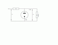
Anyway, I think I may regulate the DC on my PSU, which currently is: 275-0-275; 5V4G; 2.5uF; 10H; 60uF; 10H; 80uF = 344 VDC loaded with approx 25.8mA.
I want to add 2 0D3's in series to the PSU as they will regulate to 300V. To estimate resistor value to keep the current seen by the 0D3 to around 10mA, I added a final RC filter to my PSU. The R was initially set at 1K and the cap is set at 0.1uF (recommended as a noise bypass cap for the 0D3s - maybe not really needed?). I then set the current load to my 25.8mA PLUS 10mA for the 0D3's and began to model. I then adjusted the resistor to an NPV that results in a final B+ of around 300VDC. When I allow the 0D3's to draw 10.6mA, I get a PSUDII modelled B+ of 300.6VDC.
From this, I estimate that to use 2 0D3's in series to regulate at 300VDC, with 25.6mA tube current and around 10mA seen by the regulators, THEN I need a 680R resistor between 80uF cap and the 0D3s.
Also when I bypass the 1st 0D3 with a 100K resistor, I allow enough voltage to ensure that the second 0D3 lights-up.
My questions are:
1. Have I calculated the 680R resistor correctly?
2. Will my PSU deliver enough voltage to ensure that the 0D3 light-up properly?
3. Do I need the bypass cap?
4. Do I need the bypass cap for 0D3 #1?
Alternatively, I have used the values taken from the Tung-sol datasheet for calculating the value of the series resistor. I used 20mA for the maximum current draw for the 0D3s as I do not want to exceed the 50mA of my transformer (25.8mA from tubes, plus 20mA from 0D3s). From the Tung-Sol calculations, I get a range of series resistor values of roughly 1K to 1.5K
Which is correct - maybe NONE!
I have attached a schematic.
Thanks,
Charlie
I have been experimenting with PSUDII and with my present PSU, I get to within 2 VDC between PSUDII model and empirical measurement.
Anyway, I think I may regulate the DC on my PSU, which currently is: 275-0-275; 5V4G; 2.5uF; 10H; 60uF; 10H; 80uF = 344 VDC loaded with approx 25.8mA.
I want to add 2 0D3's in series to the PSU as they will regulate to 300V. To estimate resistor value to keep the current seen by the 0D3 to around 10mA, I added a final RC filter to my PSU. The R was initially set at 1K and the cap is set at 0.1uF (recommended as a noise bypass cap for the 0D3s - maybe not really needed?). I then set the current load to my 25.8mA PLUS 10mA for the 0D3's and began to model. I then adjusted the resistor to an NPV that results in a final B+ of around 300VDC. When I allow the 0D3's to draw 10.6mA, I get a PSUDII modelled B+ of 300.6VDC.
From this, I estimate that to use 2 0D3's in series to regulate at 300VDC, with 25.6mA tube current and around 10mA seen by the regulators, THEN I need a 680R resistor between 80uF cap and the 0D3s.
Also when I bypass the 1st 0D3 with a 100K resistor, I allow enough voltage to ensure that the second 0D3 lights-up.
My questions are:
1. Have I calculated the 680R resistor correctly?
2. Will my PSU deliver enough voltage to ensure that the 0D3 light-up properly?
3. Do I need the bypass cap?
4. Do I need the bypass cap for 0D3 #1?
Alternatively, I have used the values taken from the Tung-sol datasheet for calculating the value of the series resistor. I used 20mA for the maximum current draw for the 0D3s as I do not want to exceed the 50mA of my transformer (25.8mA from tubes, plus 20mA from 0D3s). From the Tung-Sol calculations, I get a range of series resistor values of roughly 1K to 1.5K
Which is correct - maybe NONE!
I have attached a schematic.
Thanks,
Charlie