So mainly a question out of curiosity, but is there any problem with using a single-ended output transformer with 5K and 8K taps as an ultralinear setup with a KT77 power tube? Plate voltage would be in the 350V range and transformer is rated for 15W
I realize it's not the standard 40% ultralinear tap, but I have this transformer and tube sitting around and was thinking about building something just for experimentation sake, because if it worked reasonably well it might be cool. The KT77 datasheet says it can be used as a tetrode but screen voltage should not exceed 300V (while design max is 600V for ultralinear). My datasheet has little to no info on a single-ended setup, so basically I was just checking to see if this sounded like a catastrophic failure waiting to happen or potentially doable.
Thanks.
Yes.
But if two 'ends' are available for each primary tap, then the user can just use the tap nearest the HT tap, to give the inverse, 21% tap. I.e. 4 terminals, and not 3.
No?
I have used the tap next to the anode tap on a 4k/5k2 primary for far too much feedback, the tap next to the HT worked OK.
But I am not all that impressed with "ultralinear", I've not found much gain in linearity, in my limited experiments; that was not bettered by simple local feedback
Last edited:
Hey euro, thanks - I actually didn't know how the "%" was calculated so that's useful.
And this gets to the crux of my question...if 42% is "ideal" is there a % that's just ridiculous to even consider? I realize this can get subjective quickly, just curious if any experience or scientific rationale can help provide insight.
Mondo - are you suggesting use 5K on annode and 8K screen? I would actually prefer using 5K based on past tetrode builds in these voltage ranges...switching to ultralinear could obviously change this, but if that's another option more "desirable" than 79% that is good news for me!
Thanks again.
Hi
No, I am suggesting to use the tap second nearest the HT tap (the anode at the 8k tap at the opposite end)
HT----HT----5k----8k can then become:
HT----UL----5k----8k
If there are 4 taps, the two "HT" taps arent simply a common connection, and letting:
Secondary load = 1 Ohm
Secondary volts= 1 Volt
then:
Root5k = Vprimary5k = 70.71 V
Root8k = Vprimary8k = 89.44 V
1-(70.71/89.44) = 0.21 (using the 2nd HT tap for UL connection)
0.79 FB factor, using the 5k tap for the screen, 8k for anode.
I have tried this and it can work. Nothing blew up anyways! Heavy FB was not linear at all....and probably a little unstable.
The HT 'end' tap, was better, but I didnt pursue it further and left UL there.
Big down side, but I guess true for all UL designs, is I'd guess an easy route for noise to enter, via the screen, not having it's own well filtered supply.
If you then decide maybe a lower impedance primary might work better you can then move to the 5k tap at the anode, and leave the connection on the HT as it is, 8k HT tap used for supply meaning the 5k HT tap is still free for UL.
In that case the reflected impedance is somewhere between 5k and 8k. Say 6k5.
Although I think I have made a mistake somewhere, with the %
Last edited:
Ahhh, interesting - thanks for detailed explanation but unfortunately my OT is just three taps (COM, 5K and 8K).
Basically what you have is a primary with three connections:
0% (com)
79% (5 kOhm)
100% (8 kOhm)
Flip it and you'll have:
0% (ex 8 kOhm, now com)
100-79=21% (ex 5 kOhm, now UL)
100% (ex com, now 8 kOhm)
0% (com)
79% (5 kOhm)
100% (8 kOhm)
Flip it and you'll have:
0% (ex 8 kOhm, now com)
100-79=21% (ex 5 kOhm, now UL)
100% (ex com, now 8 kOhm)
Whoa, very interesting - did not know that was possible. Would secondary need to be flipped as well? It has COMM/4/8/16 taps. Thanks
Basically what you have is a primary with three connections:
0% (com)
79% (5 kOhm)
100% (8 kOhm)
Flip it and you'll have:
0% (ex 8 kOhm, now com)
100-79=21% (ex 5 kOhm, now UL)
100% (ex com, now 8 kOhm)
Good point Zintolo
Secondary is:
0% (com)
50% (4 Ohm)
70.7% (8 Ohm)
100% (16 Ohm)
Flipping it you’ll get:
0% (com)
29.3% (1.4 Ohm)
50% (4 Ohm)
100% (16 Ohm)
Not the best scenario, but obliged if your amp has nfb from secondary.
What impedance have your speakers?
I’d reverse speakers connections instead.
0% (com)
50% (4 Ohm)
70.7% (8 Ohm)
100% (16 Ohm)
Flipping it you’ll get:
0% (com)
29.3% (1.4 Ohm)
50% (4 Ohm)
100% (16 Ohm)
Not the best scenario, but obliged if your amp has nfb from secondary.
What impedance have your speakers?
I’d reverse speakers connections instead.
I'm not sure that you would gain from driving that tube as UL 20% into the 8K OT windings compared to just running it in pure triode mode into the 5K windings.
I suppose if you hooked 8 ohm speakers to the 16 ohm taps, the winding ratio would make the tube see the 8K windings as a 4K load which might work. You also have to consider the DC resistance of the 5K vs the 8K. And it's making the OT work in a way it was never designed to.
I'm just not sure how great a KT77 would drive into an 8K load, the extra DC resistance (lower plate voltage) and if 20% UL is worth all that effort. But might be fun to build it as a Triode and then play with swapping stuff around and see what it sounds like. Might take some local NFB to clean it up in UL mode.
Very cool, thanks....speaker is 8 ohms unfortunately. So flip primary, keep secondary, flip speaker outputs and I'll get to use 4/8/16 like normal? That'd be great since I like to go through an impedance selector. Oh, and yes - I was not incredibly optimistic about putting 8K primary on KT77, but figured it might be fun to experiment with it. Zintolo - on your second comment are you suggesting a plate resistor on the power tube?
Last edited:
What we were suggesting is:
- flip primary and connect as per my post;
- flip secondary and connect 8 ohm speaker into 16 Ohm output;
- connect speakers without flipping the cables.
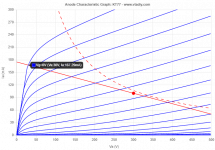
You'll get 21% UL and 4 kOhm Ra (see my draft of loadline in previous post).
- flip primary and connect as per my post;
- flip secondary and connect 8 ohm speaker into 16 Ohm output;
- connect speakers without flipping the cables.
You'll get 21% UL and 4 kOhm Ra (see my draft of loadline in previous post).
- Home
- Amplifiers
- Tubes / Valves
- Using SE Output Xfmr with 5K and 8K Impedance as Ultralinear?