Thanks, Tim - I have a Rubycon MXH 82uf 600V snap-in cap I was planning to use and it measures 73uf, which is why I have C1 set to that value!
I set the bias on the KT120s at 75mA each but I've added 7.5mA for the screens, which are connected to the 44% taps of the output transformers. That is how I get the 330mA for the I1 current tap.
I set the bias on the KT120s at 75mA each but I've added 7.5mA for the screens, which are connected to the 44% taps of the output transformers. That is how I get the 330mA for the I1 current tap.
That's a lot of dissipation, and likely a significant increase over the enclosures original status - are you including enhanced cooling? I can see your photos and long thread on stereonet that indicates 370V 400mAdc rating for the PT secondary.
I don't see any frequency spectrum or squarewave or other testing related to low and high frequency response and stability. Have you seen the A3600 go through that, as a way of indicating how close you may be to unstable operation given the global feedback?
I don't see any frequency spectrum or squarewave or other testing related to low and high frequency response and stability. Have you seen the A3600 go through that, as a way of indicating how close you may be to unstable operation given the global feedback?
Thanks, Tim! No, I haven't done any scope testing. I would love to do so but I don't have one... I do have a Zoyi ZT-702S digital oscilloscope I could try out but I'd rather get confident on other less beefy circuits first). The original output tubes (8045G) were triodes rated for 45W max plate dissipation with heater draw of 2.5A. I've read they were often biased hot and had a habit of failing and were discontinued decades ago.
The KT120s are 60W with a heater draw under 2A. I think the output transformers are dealing with just under 80W each but the covers never get even remotely warm to the touch. The multi-section caps are mounted on top of the chassis and they don't get warm even though they are within a couple of centimeters of the PT. The tubes get hot, obviously, and the power transformer gets warmer over time until it gets to about 40C (according to IR heat gun) after a few hours. The choke gets pretty warm, too, but not as warm as the PT. I've noted hot spots on the PCB, so I got to the point of copying it and having new ones produced by PCBway. I've just received the components I need to populate one of the boards, which will be a future project.
The global feedback has been increased from stock, likely when the output tubes were changed to KT88s (there are instructions to do so for stability reasons). I have had problems in the past with motorboating at V6 and I've noticed that this tube runs about 15C hotter than the others (180C vs 165C as read by IR heat gun). I wonder if I have a leaky decoupling capacitor (they are reasonably new auricaps but you never know?). I have wondered if I should go back to stock resistors and capacitors wrt GNFB (I have the components ready to go!).
I saw the comments on motorboating. A scope would help with confidence that there was no snivet oscillation, or something else quirky that may not be audible. Even your scope should be able to show if there was something NQR. Do you know anyone in Sydney who has done that type of testing? It's a learning curve to put that form of instrumentation together, or go the soundcard and software route, for frequency spectrum and other such testing. Anything with global feedback is a risk.
It looks like the OT secondary wiring that goes from OT, to speaker terminals, to pcb feedback parts, is quite separated and could be prone to noise/signal ingress - compared to keeping the com and speaker wiring closely coupled (eg. twisted) from OT to speaker terminals, to pcb. I can't tell if each com black wire is directly returning to its feedback 100R.
Somewhat similarly, the main DC feed to each OPT is commoned and comes from the choke terminal, rather than separately coming from the main filter cap terminal. I can't tell if common cathode black daisy chain goes directly to the main filter cap terminal.
Yes, I have been interested in the GNFB circuit for some time but I've not touched it yet because I understand I really need a scope before I muck around with the values there already, which seem to be working fine, so far (touch wood). I have found a contact in Sydney just recently who knows this unit and I'll reach out to him to see if I can bring my unit to him for a looksee on his scope.
As for the grounding scheme, I have the assembly manual(!) and I've taken a pic that might shed some light. The wires shown are all the ground wires!

As for the grounding scheme, I have the assembly manual(!) and I've taken a pic that might shed some light. The wires shown are all the ground wires!
BTW - you have likely noticed from my StereoNet threads that I have already replaced the old multi-section PS caps in my unit, first with almost a like-for-like replacement (100uf, 100uf, 50uf, 50uf) and then with a little reconfiguration (50uf, 100uf+100uf, 50uf, 10uf film cap). I wasn't getting much advice there on my PS tinkering so someone suggested I post here. I thought I should start here with a simple proposition - given the original design, is my new proposed design, come up with via PSUD2, both a safe one and better performing?
Granted, the question is a little more complicated, given the circuit alterations made as a result of the change in output and phase inverter tubes (8045G to KT88 to KT120; 6240G to 6GU7).
Granted, the question is a little more complicated, given the circuit alterations made as a result of the change in output and phase inverter tubes (8045G to KT88 to KT120; 6240G to 6GU7).
Ta. I'm not a fan of the assembly manual technique, as it doesn't separate each channel's speaker output com line back to the relevant summing node of the pcb, but rather commons the com lines and takes them via the screen supply filter cap neg (if I am reading it correctly). Also, the output stage bias gnd is from the screen supply filter cap neg and not the output stage filter cap neg. And the output stage channel commons are daisy chained to the output stage filter cap neg, rather than separated per channel.
Thanks, Tim - on each of your suggestions:
- Would it be better to replace the wire between R and L speaker commons (#16) with one running from R speaker common back to the negative terminal of the Output stage bias supply cap like #15? I'm not sure where I would connect #15 and #16 wires to the PCB?
- I'm confused about your second suggestion - do you mean that I should run the wire between the negative terminals of the bias supply cap and the second PS filter cap directly to the first filter cap (one on the far right)?
- I could run wire #11 back to the negative terminal of the second PS filter cap like #9?
Wiring changes are unlikely to show any differences, as they relate to subtle issues that may or may not be measurable, and it would depend on the test conditions. The manufacturer's wiring diagram appears to make it easier and simpler to construct, and so avoid construction mistakes and diagrams that may be more difficult to interpret. I'm just making the comments as a form of advise and awareness of where noise/distortion/cross-coupling could be ingressing if that topic is of interest, but noting that when one looks hard enough there are many other causes that could completely dominate such a general topic as noise/distortion/cross-coupling.
The comment about the speaker common wiring is that each channel's output is perhaps best wired so that it is independent of the other channel, and as such the OT winding com wire for a channel returns to the bottom end of the 100R resistor across which the feedback is being applied for that channel. That com wire can be loosely twisted with the active wire to minimise the chance of unrelated noise/signal ingress into the wiring loop (given it traverses across the chassis for some distance). If a com wire for one channel has a path that could pick up residual voltages due to other current flow (like from the other channel, and from power supply related currents) then those residual voltages can enter the signal chain for that channel as a form of noise/distortion/cross-coupling.
The output stage bias voltage acts on the output valves voltage signal between grid to cathode terminals. The cathode terminal for each channel is a daisy chain link back to the 'middle' filter cap neg, and so any noise/signal voltage between the filter cap negs (across the link), gets added to the bias voltage as a form of noise/distortion/cross-coupling.
Yes the addition of a separate return wire back to the second filter cap neg, for each channel's output stage, could avoid cross-coupled signal between channels.

Thanks, Tim - I am interested in understanding grounding better so will come back to this after I've made changes to the filter caps. This thread has raised concern that the JJ 560V caps I have installed right now are a light on current ripple so I will get on and make changes there first.
I know you were concerned about the current running through the choke. I've looked at the choke's capacity to take the current by way of chasing down info on the C2006 choke installed but would like your opinion. AFAIK, the 8045Gs used to be biased hot (over 70mA each) and were generally wired in triode configuration (ie no screen tap connection for UL config). I've translated a few Japanese blogs that remarked on how high the voltage of the output stage is and how many watts the amplifier was putting out (over 70W) above the advertised 50W. I think the current draw of my amp at idle is pretty close to 350mA, which is 50mA below the 400mA at which the choke is supposed to present a 0.35H impedance. I note the choke does not have the max mA value stamped on it where it should.
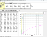
I have not found any datasheet for the C2006 choke but I have found two catalogues containing charts of Impedance (H) vs current
(mA) of chokes available at the time (see below).

The curves here suggest the impedance of the C2006 choke in my unit will be higher if the current is lower than the value on the sticker (400mA in this case) and lower if the current is higher. This behaviour could be part of the reason there is no max current value stamped on the choke. Therefore, I imagine my main issue is to ensure the current draw is not so great the choke overheats to a point where it causes the black goo it is encased in to leak out?
In the PSUD model, I've tested many C1 to C4 cap values with combinations of choke impedance (300-500mH in 100mH steps) and variations in two current steps (350&450mA). As you have advised, PSUD modelling of step changes is far from conclusive, but I've run so many combinations of cap and choke impedance values I can at least safely say the values I'm proposing (and those thereabouts) are promising and do not show any signs of oscillation or other funny business (noting the outstanding GNFB question mark)?
Finally, I would appreciate your view on this question: Is it better (ie lower distortion of music input signal) to front load your ripple rejection as I am proposing (ie small values for C3 and C4 of 10uf and 1uf) or to keep them at larger values to slow down the voltage response? For example, I could use an Al-ELko 16uf triple-section cap I have for C3 (16uf x2) and C4(16uf).
I know you were concerned about the current running through the choke. I've looked at the choke's capacity to take the current by way of chasing down info on the C2006 choke installed but would like your opinion. AFAIK, the 8045Gs used to be biased hot (over 70mA each) and were generally wired in triode configuration (ie no screen tap connection for UL config). I've translated a few Japanese blogs that remarked on how high the voltage of the output stage is and how many watts the amplifier was putting out (over 70W) above the advertised 50W. I think the current draw of my amp at idle is pretty close to 350mA, which is 50mA below the 400mA at which the choke is supposed to present a 0.35H impedance. I note the choke does not have the max mA value stamped on it where it should.
I have not found any datasheet for the C2006 choke but I have found two catalogues containing charts of Impedance (H) vs current
(mA) of chokes available at the time (see below).
The curves here suggest the impedance of the C2006 choke in my unit will be higher if the current is lower than the value on the sticker (400mA in this case) and lower if the current is higher. This behaviour could be part of the reason there is no max current value stamped on the choke. Therefore, I imagine my main issue is to ensure the current draw is not so great the choke overheats to a point where it causes the black goo it is encased in to leak out?
In the PSUD model, I've tested many C1 to C4 cap values with combinations of choke impedance (300-500mH in 100mH steps) and variations in two current steps (350&450mA). As you have advised, PSUD modelling of step changes is far from conclusive, but I've run so many combinations of cap and choke impedance values I can at least safely say the values I'm proposing (and those thereabouts) are promising and do not show any signs of oscillation or other funny business (noting the outstanding GNFB question mark)?
Finally, I would appreciate your view on this question: Is it better (ie lower distortion of music input signal) to front load your ripple rejection as I am proposing (ie small values for C3 and C4 of 10uf and 1uf) or to keep them at larger values to slow down the voltage response? For example, I could use an Al-ELko 16uf triple-section cap I have for C3 (16uf x2) and C4(16uf).
Choke inductance varies with dc current, but also ac voltage across it, although the drooping inductance characteristic from increasing dc current in those choke curves is typical. PSUD2 can estimate the Vac across the choke, by the rms value in the data, although that does include a Vdc drop due to dc resistance. Only some choke data shows the test Vac and Idc for a given inductance. The following link is to an article on how to measure those levels yourself if you want to go that far. Wrt to overheating, the measured dc resistance will change with internal temperature, so better to heat the choke up (eg. by passing 400mA for 10-20 minutes) and then measuring dc resistance. That dc resistance will then give you an estimate of internal power loss (eg. your PSUD2 indicates 11 ohm DCR, so 1.8W - which is reasonably low, so power dissipation may not be the reason for the 400mA rating per se). https://www.dalmura.com.au/static/Choke measurement.pdf
I'd suggest that C2 is where to locate the most capacitance, if you have a choice. C2 has to not only suppress 100/120Hz ripple voltage, but imho more importantly the full audio frequency range of signal current that loops through it from both channels - and that frequency range can extend well below 50Hz. Also be aware that global feedback suppresses disturbances that aren't in the original signal, which includes signal changes due to B+ variation (such as from load changes and mains ripple, and many other subtle forms of disturbance such as microphonic signals).
Also remember that ecap rated life can vary a lot due to the actual datasheet spec, and how much under the rated cap temp you can operate. And like output stage tubes, you need to program in replacement, so if a valve or a cap is within its rated life then most will keep using it, but counter to that is that many then just wait for such a part to fail before replacing it (and cross their fingers about collateral damage to other parts).
Those JJ 560V VNH have a comparatively low max temp of 70C (rather than 85C, or 105C), and short life of 1khr. In comparison, the Rubycon MXH 82uF has a 3khr 105C rating - which ballpark relates to 3x2x2x2 = 12x longer life assuming the same ripple current rating, based on double life for each drop of 10C below limit temp.
Thanks, Tim, for sharing your advice and experience - I much appreciate it! Apologies, for the confusion using impedance when I meant to say inductance wrt to Henries.
I wasn't aware the DC resistance of the choke varies under load! I've measured the C2006 choke in my unit and it measures 11ohm as per the stamp on the 'sticker' - how much should I model it increasing to, do you think? Hmmm... thinking about it, it would explain why V(I2) (plate voltage for phase inverter) reduces slowly as time passes by up to maybe 10V from the initial (after warmup) value, as I play music? There are a few test points on the PCB I have been taking readings from to understand how the amp behaves and to check everything is as it should be.
Finally, thanks so much for your advice re cap values. I will make those changes once my 1uf cap arrives. At the same time, I will look at the ground wiring and come back with my results. I think I get what you mean about the speaker common wiring changes. The 100ohm tail resistor on the 6AQ8 input tube is connected to the common ground plane on the PCB very close to where E1 and E3 are drawn in the manual picture above.
If you google copper wire resistance's temperature coefficient, and then estimate the temperature difference between ambient and what could be inside the choke, then that will indicate the operating DCR of the choke. You won't know the internal temp rise for sure, and the temp doesn't rise uniformly on the whole winding, which is why a test may be more informative for you. But I doubt the B+ to the output stage would droop significantly due to DCR rise, as even cold DCR indicates only circa 2V drop.
High Ripple current snap in capacitors. Mouser
Mfr. Part #
ALH82A101CC550
Mouser Part #
80-ALH82A101CC550
3.3 amps ripple current 550 volt 100uF.
Mfr. Part #
ALH82A101CC550
Mouser Part #
80-ALH82A101CC550
3.3 amps ripple current 550 volt 100uF.
OK, so my thinking has moved on a little more. I have bought and received a 75uf 600V version of the Kemet cap TAG has recommended, which handles 970mA of ripple current at 100Hz (a 100uf one is too big for the choke/C2 combo). Also, I found my calcs about ripple on the fourth stage were a bit off. I looked at ripple of R3 after 30 seconds and found the original PS config shows under 10uf while my current config shows about 36uf - still very minimal but I wanted to get closer to the original figure.
I've decided to use a 16uf triple section cap from F&T for the third and fourth stages. This way I can use one section as C3 and then split the PS and use the other two sections for each side of the signal tube? That will require two closely matched R2 plate resistors and R3 bleed resistors (the capacitance of each of the three 16uf sections are closely matched). If I do this split, do I double the value of R2 and R3 to 200kohm and 660kohm, respectively? And I'm guessing I would halve the 20uf ripple that shows up in the PSUD model results?
Voltage chart on startup:

Voltage chart after 100mA increase at 15.1 seconds:

Current chart on startup:

Current chart after 1 second:

I've decided to use a 16uf triple section cap from F&T for the third and fourth stages. This way I can use one section as C3 and then split the PS and use the other two sections for each side of the signal tube? That will require two closely matched R2 plate resistors and R3 bleed resistors (the capacitance of each of the three 16uf sections are closely matched). If I do this split, do I double the value of R2 and R3 to 200kohm and 660kohm, respectively? And I'm guessing I would halve the 20uf ripple that shows up in the PSUD model results?
Voltage chart on startup:
Voltage chart after 100mA increase at 15.1 seconds:
Current chart on startup:
Current chart after 1 second:
Attachments
So finally the stars aligned and I spent a few hours today reconfiguring the power supply of my Luxman (Luxkit) A3600. I bought myself a multi-function tester T7, which I need to measure the transistors on another project (broken Luxman C03 preamplifier) and tested my new power supply caps for fun. I got different (more accurate?) capacitance readings, which I've plugged into PSUDII and I chose the following caps:
C1 - Kemet 75uf (measures 82uf) 600V capacitor (ALH82A750CB600) with 970mA ripple current at 100Hz
C2 - Kemet 390uf (measures 352uf) 600V capacitor (ALH82A391DL600)
C3&4 - F&T triple section 15uf (measures ~18uf) 550V capacitor
I also tested the C2006 0.35H 400mA (though no value under Max mA heading) 11ohm choke with a replacement I bought off Yahoo Auction Japan for not much money. My T7 meter indicated 1.4H inductance for the new choke and just over 1H for the old one (both unloaded, of course). The old one had leaked badly at some point in its life so I swapped it over.
Here is what PSUDII made of my choices...


I changed the value of R1 from 1.5Kohm to 2Kohm to reduce B2 (V(I2)) closer to the voltage (470V) in the original schematic. My PSUDII approximation was not far away from what I measured - PSUDII indicates B2 of 477V and I measured 471V after an hour playing music. PSUDII suggests B3&4 (V(R3)) of 262V and I measured 258V. I expect this means B1 (V(C2)) is more than 6V below PSUDII's value of 522V, so perhaps around 515V?
According to PSUDII (50ms after 30 second reporting delay), ripple rejection is mostly improved with 512mV at V(I1) compared with 1.2V in original config, 23mV at V(I2) cf 36mV, 20uf at V(R3) cf 10uf.
My main motivation for this PS change was to improve the capacitor configuration to eliminate the potential for any ringing, which may be audible, but mostly to ensure caps were capable of handling the ripple modelled in PSUDII. I have really enjoyed the challenge and learned a lot - thanks to @trobbins and @Tubesaregreat for sharing your advice - I much appreciate it! Note I didn't alter the ground wiring in the end because I didn't want to add other changes to this PS config change and the job would have taken more time I didn't have (it would take a bit of work to extract the offending wire from the existing 'loom' of wires. I've added this job to my list.
As for my impressions from the listening session - I like what I hear so far! It definitely hasn't gone backwards and I'm getting more of a sense of "being in the room". I have many more tracks to play before I can be confident about this first impression.
C1 - Kemet 75uf (measures 82uf) 600V capacitor (ALH82A750CB600) with 970mA ripple current at 100Hz
C2 - Kemet 390uf (measures 352uf) 600V capacitor (ALH82A391DL600)
C3&4 - F&T triple section 15uf (measures ~18uf) 550V capacitor
I also tested the C2006 0.35H 400mA (though no value under Max mA heading) 11ohm choke with a replacement I bought off Yahoo Auction Japan for not much money. My T7 meter indicated 1.4H inductance for the new choke and just over 1H for the old one (both unloaded, of course). The old one had leaked badly at some point in its life so I swapped it over.
Here is what PSUDII made of my choices...
I changed the value of R1 from 1.5Kohm to 2Kohm to reduce B2 (V(I2)) closer to the voltage (470V) in the original schematic. My PSUDII approximation was not far away from what I measured - PSUDII indicates B2 of 477V and I measured 471V after an hour playing music. PSUDII suggests B3&4 (V(R3)) of 262V and I measured 258V. I expect this means B1 (V(C2)) is more than 6V below PSUDII's value of 522V, so perhaps around 515V?
According to PSUDII (50ms after 30 second reporting delay), ripple rejection is mostly improved with 512mV at V(I1) compared with 1.2V in original config, 23mV at V(I2) cf 36mV, 20uf at V(R3) cf 10uf.
My main motivation for this PS change was to improve the capacitor configuration to eliminate the potential for any ringing, which may be audible, but mostly to ensure caps were capable of handling the ripple modelled in PSUDII. I have really enjoyed the challenge and learned a lot - thanks to @trobbins and @Tubesaregreat for sharing your advice - I much appreciate it! Note I didn't alter the ground wiring in the end because I didn't want to add other changes to this PS config change and the job would have taken more time I didn't have (it would take a bit of work to extract the offending wire from the existing 'loom' of wires. I've added this job to my list.
As for my impressions from the listening session - I like what I hear so far! It definitely hasn't gone backwards and I'm getting more of a sense of "being in the room". I have many more tracks to play before I can be confident about this first impression.
As for splitting the triple section cap to use two sections to provide separate B3 and B4 (left and right) supplies for the input signal tube, this option has also been added to my task list for this amp that I will get to later.
Incidentally, I rate the advice from DHTRob to go big on C2 and keep C1 just high enough to provide the B+ you want and provide a smooth response to sudden swings in current. He suggests the jerky nature of a transition creates unwanted harmonics and I've found there might be proof in this pudding.
As for use of PSUDII, while it is time saving to just model the B+, I've also found it very useful to consider all of the power rails in the power supply, too. I can easily check the residual ripple on each of them and how much effect they have on each other.
Also, the more ripple you deal with in your choice of values you choose for C1 and C2, the less capacitance you need for C3 and C4. The lower capacitance you can get away with at C3 and C4, the more dynamic your power supply seems to be. Again, my experience is that this provides an improvement in sound quality.
Finally, if I had a clean slate, I would have a DC link capacitor for C1 and small film capacitors (~10uf) for C4, one for each channel. However, I don't have the room inside the amp and don't want to mess about with the layout more than I already have. Anyway, I hope this is of some use to people interested in the power supplies of their amplifiers.
- Home
- Amplifiers
- Power Supplies
- Using PSUD to optimise power supply in my KT120 amplifier