There are a lot of sellers offering matched pairs of output pentodes but none of them defines which parameters of the tube pair are matched.
My question is a general one:
In a PP output stage with two independent adjustable CCS (one in every cathode) for automatic bias, I could adjust the plate current of the two pentodes to arbitrary equal value.
Isn't that matching enough?
My question is a general one:
In a PP output stage with two independent adjustable CCS (one in every cathode) for automatic bias, I could adjust the plate current of the two pentodes to arbitrary equal value.
Isn't that matching enough?
The transconductance should also be matched at the operating points for lower distortion.
Last edited:
Thank you for the hints.
So transconductance is Ia/Ug1 and should be equal for both PP tubes in the operating point. This parameter is fixed by the tube but...
What if I adjust the AC amplitudes on both grids independently by simple resistive dividers?
Could that work?
So transconductance is Ia/Ug1 and should be equal for both PP tubes in the operating point. This parameter is fixed by the tube but...
What if I adjust the AC amplitudes on both grids independently by simple resistive dividers?
Could that work?
Many amps have an AC balance control located earlier in the circuit to compensate for
imbalances in the various stages. Often it's a pot in the plate circuit of the driver stage.
See the manual page 17 here:
https://www.arcdb.ws/Database/D76/ARC_D51_D75_D75A_D76_D76A_manual.pdf
Or the schematic here:
Harman Kardon Citation II Stereo Power Amplifier Manual | HiFi Engine
imbalances in the various stages. Often it's a pot in the plate circuit of the driver stage.
See the manual page 17 here:
https://www.arcdb.ws/Database/D76/ARC_D51_D75_D75A_D76_D76A_manual.pdf
Or the schematic here:
Harman Kardon Citation II Stereo Power Amplifier Manual | HiFi Engine
Last edited:
I'd guess that the majority of the tubes advertised as being matched are really not. Just something that every seller states. How exactly do you match rectifier tubes?
By voltage drop at a particular current. Otherwise you'd have to add low value series resistors
to each to help balance them despite normal variation.
to each to help balance them despite normal variation.
Last edited:
Yes, thank you, that seems to be the most appropriate way for compensating a difference in transconductance of the output tubes.Many amps have an AC balance control located earlier in the circuit to compensate for
imbalances in the various stages. Often it's a pot in the plate circuit of the driver stage.
I don't.How exactly do you match rectifier tubes?
IMHO a difference in the half waves of rectified sine does not matter.
Or does it?
Matched Plate characteristics on rectifier tubes?
Consider this:
Most manufacturers are too cheap to put a center tap on the rectifier 5V filament winding.
Only one side of the 5V winding is the B+ output (instead of an expensive center tap).
So . . .
Plate 1. 350V + 5V = 355V
Plate 2. 350V + 0V = 350V
How matched is that?
(don't worry, it is not that big of a deal, unless you do not use a good B+ filter circuit).
ah, that is matching? all the while i was thinking plate matching... 😀
what is the difference if you just take the dc output at one end of the filament cathode?
why go thru the trouble of insisting on a filament center tap?
btw, unless you wind the filament winding bifillar, then matching is a hard act....
i have seen power traffos coming from the states that merely soldered a center tap connection by scratching the copper conductor on the center tap position and then soldering in a pigtail connection of the winding...yes, that can be done if that is what you want..
what advantages will an exact center tap bring?
Last edited:
TonyTecson,
It is not really important, but if you have the center tap, and use it to pull the B+ from, then you are rectifying:
Either:
Plate 1. 350V + 2.5V = 352.5V
Plate 2. 350V + 2.5V = 352.5V
Or:
Plate 1. 350V - 2.5V = 347.5V
Plate 2. 350V - 2.5V = 347.5V
(depending on how you wire the B+ secondary and 5V filament secondary relative phases).
Or, you can use resistors in a Pseudo Center Tap.
All the above is just one of the very inner layers of the onion, I never worry about it.
And yes, another inner layer of the onion is the un-equal DCRs of the 2 halves of the secondary.
Remember, this all started because someone was worried about the matching of the rectifier plate characteristics.
So, I had to bring that "Problem" into perspective (and you brought out the Bifilar issue . . . matched DCR).
Last edited:
Do not loose any sleep over it.
Using a rectifier with plates tied together, for one phase
and another rectifier with plates tied together, for the other phase
might cause some un-balance, especially if the two tubes are by two different manufacturers, and the construction is totally different.
But again, it is usually not a problem.
for 60 Hz mains, full wave rectification, the main ripple is at 120Hz. The 60 Hz un-balance is smaller than the 120Hz ripple, but the capacitive reactance of the capacitors is 2 times as high at 60 Hz, the frequency of the un-balance ripple, the filter effect is not as good at 60 Hz.
Details like that are mostly for those who worry.
Last edited:
No.There are a lot of sellers offering matched pairs of output pentodes but none of them defines which parameters of the tube pair are matched.
My question is a general one:
In a PP output stage with two independent adjustable CCS (one in every cathode) for automatic bias, I could adjust the plate current of the two pentodes to arbitrary equal value.
Isn't that matching enough?
That does not tell how Gm is matched, you need additional controls and
external instrumentation to adjust this.
Get matched tubes, tubes that is matched at typical working conditions. Also
demant that matching method is documented.
What if I adjust the AC amplitudes on both grids independently by simple resistive dividers? Could that work?
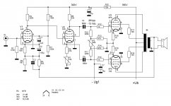
If the output tubes are not very un-matched, Simple DC- and AC-balance adjustments give acceptable result.
Attached one of my schematics that works well with "typically" matched output tubes.
P1 is for AC-balance and P2 for DC.
Attachments
Thank you all!
Now a question with increased difficulty:
Is there anything at the G2 (screen grids) of the output pair that should be balanced too?
Now a question with increased difficulty:
Is there anything at the G2 (screen grids) of the output pair that should be balanced too?
Not on a matched pair.Thank you all!
Now a question with increased difficulty:
Is there anything at the G2 (screen grids) of the output pair that should be balanced too?
- Home
- Amplifiers
- Tubes / Valves
- Using non matched pair of output tubes