Hello, I’m repairing a Yamaha CR-2020 and performing the service bulletins. It recommends replacing the two regulators TR712 and TR715 as the originals get too hot. The recommendation is to use the TIP41C. I can place an order for them if needed, but I have a few dozen each of the MJE15032 and MJE15034 and would much prefer to use those if they’ll work or be even better.
Thoughts? Would it be better to use the 15032 or 15034, which of the two would be a better fit?
Dan
Thoughts? Would it be better to use the 15032 or 15034, which of the two would be a better fit?
Dan
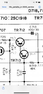
The originals are 2SD234 which are clearly not robust enough. I’m in the middle of doing a repair and it’s torn down so I can’t take measurements. The manual states 28.5v on the emitter, 37.5V on the collector, and its really hard to read, but looks like 23.8v on the base. Currents not sure.
The 15032 is rated for higher voltages (vce, vcb, veb) and higher current rating than the TIP41C. Slightly lower current for the 15034. So I don’t think voltages and currents would be an issue, but maybe another reason it wouldn’t work?
Dan
The 15032 is rated for higher voltages (vce, vcb, veb) and higher current rating than the TIP41C. Slightly lower current for the 15034. So I don’t think voltages and currents would be an issue, but maybe another reason it wouldn’t work?
Dan
2SD234 is 50 V, 3 A >40 Hfe @0.5 A if not sorted and just 3 MHz
TO-220 package is limiting
The TIP41C is 100V, 6 A, >30 Hfe @0.3A, still TO-220 but with higher power rating from a bigger die.
That base voltage cannot be right
TO-220 package is limiting
The TIP41C is 100V, 6 A, >30 Hfe @0.3A, still TO-220 but with higher power rating from a bigger die.
That base voltage cannot be right
2SD234 is 50 V, 3 A >40 Hfe @0.5 A if not sorted and just 3 MHz
TO-220 package is limiting
The TIP41C is 100V, 6 A, >30 Hfe @0.3A, still TO-220 but with higher power rating from a bigger die.
That base voltage cannot be right
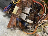
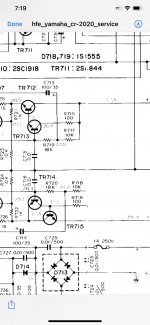
Well the manual is really hard to read, here is a pic from that part of the schematic. You’ll be looking at TR712 and TR715. The voltages I gave you are from TR712. It does seem like they’re different, like their base and emitter voltages are swapped.
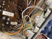
I have also included photos of the heat sink. What many do is attach those heat sinks to the chassis just below the meter lights allowing the chassis to eat some of that heat, that’s the plan.
Dan
Attachments
Last edited:
Rather than only focusing on "better datasheet specs" parts I´d try to improve heatsinking.
Well unfortunately that’s all I can go off of right now is the data sheets. I didn’t state it, but already had planned on improving the cooling of the devices, but improved heatsinking isn’t going to bring two dead components back to life, so I’ll still need to find replacements.
I’ve read a few different places in diyaudio that the MJ150XX would make fine replacements for the TIP41C, just making sure that’s true in this instance.
Dan
Are those heatsinks isolated, I bet they have just screwed the collector tabs to the sinks
The bigger transistor really won't help much. A sink that size can only handle a couple of Watts in natural convection.
The bigger transistor really won't help much. A sink that size can only handle a couple of Watts in natural convection.
Are those heatsinks isolated, I bet they have just screwed the collector tabs to the sinks
The bigger transistor really won't help much. A sink that size can only handle a couple of Watts in natural convection.
They are isolated, only touching the collector. A bigger one will help in a way as it’ll handle the heat better than the original, but I’ve already mentioned twice that I’ll be improving the heatsink, mounting it to the chassis. I will make sure to electrically isolate it. You can forget the heat sink, it’ll be taken care of.
That being said, I can’t get the originals anyway, they’re no longer made. So I’m trying to find a suitable replacement, preferably what I have on hand.
Dan
If anyone runs by this thread in the future, the answer is yes, they will work in this position. I received an answer on a Yamaha forum from a tech that hangs out there.
Dan
Dan
In a nutshell:
1) since you are replacing them, get same or better specs tansistors.
2) and again, your problem there is skimpy heatsinging rather than anything else.
2 possible solutions:
a) mount new transistors on improved heatsinks which will fit lsewhere, not fit there and so require some extra wires.
Not Audio but DC there, won´t be affected by a few inches of wire.
b) *maybe* you can get better (black, extruded and finned individual heatsinks instead or current unfinished flat folded sheet aluminum.
Similar to:
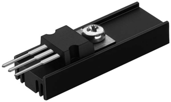
take about same board space, are much improved, just remember to glue them to PCB to avoid vibration cracking transistor legs.
1) since you are replacing them, get same or better specs tansistors.
2) and again, your problem there is skimpy heatsinging rather than anything else.
2 possible solutions:
a) mount new transistors on improved heatsinks which will fit lsewhere, not fit there and so require some extra wires.
Not Audio but DC there, won´t be affected by a few inches of wire.
b) *maybe* you can get better (black, extruded and finned individual heatsinks instead or current unfinished flat folded sheet aluminum.
Similar to:
take about same board space, are much improved, just remember to glue them to PCB to avoid vibration cracking transistor legs.
- Home
- Design & Build
- Parts
- Using MJE1503X in place of TIP41C regulators for power supply