For some time I would like to have an audio-transformer suitable for measurements of class-D-amps with BTL-output configuration
that will be converted from symmetric output to asymmetric scope input.
With the primary driven by low impedance amp and the secondary more or less unloaded best signal integrity may be expected.
The problem is non-linearity of the magnetic core increasing drastically with signal level and to low frequencies.
There exist special magnetic highly linear materials, but not available to me.
And available audio line-in transformers cannot handle loudspeaker levels.
They simply are too small, here it is size that matters.
So why not use one off-the-shelve toroid mains-transformer -
connecting the primary 230V winding to the amp
and the secondary to the scope.
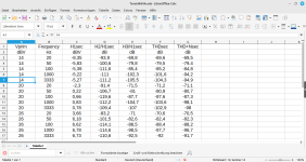
In my stash I discovered an 48VA toroid with 24V secondary, giving close to 10:1 or 20dB attenuation.
I think there is nothing special with this, so similar transformers might yield similar results.
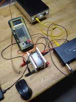
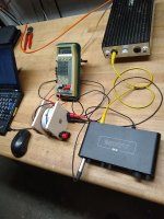
For the test I fed the primary with my MOSFET-Class-AB-Mono-Block, driven by the MOTU M4 soundcard.
The secondary was connected with the input of the soundcard.
Sample frequnency was set to 192kHz.
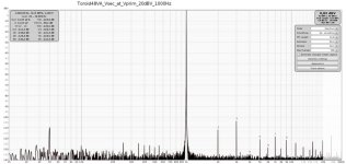
Here is the summary of THD measurement at various levels and frequencies.
All in all this is much better than I expected after disappointing measurements of audio line and mic transformers.
that will be converted from symmetric output to asymmetric scope input.
With the primary driven by low impedance amp and the secondary more or less unloaded best signal integrity may be expected.
The problem is non-linearity of the magnetic core increasing drastically with signal level and to low frequencies.
There exist special magnetic highly linear materials, but not available to me.
And available audio line-in transformers cannot handle loudspeaker levels.
They simply are too small, here it is size that matters.
So why not use one off-the-shelve toroid mains-transformer -
connecting the primary 230V winding to the amp
and the secondary to the scope.
In my stash I discovered an 48VA toroid with 24V secondary, giving close to 10:1 or 20dB attenuation.
I think there is nothing special with this, so similar transformers might yield similar results.
For the test I fed the primary with my MOSFET-Class-AB-Mono-Block, driven by the MOTU M4 soundcard.
The secondary was connected with the input of the soundcard.
Sample frequnency was set to 192kHz.
Here is the summary of THD measurement at various levels and frequencies.
All in all this is much better than I expected after disappointing measurements of audio line and mic transformers.
Attachments

I would add a coupling cap to the primary. A little DC offset could saturate that transformer making for high distortion.
Using a transformer, it is usually not possible to obtain distortion that is low enough for measurement purposes, with the exception of a (really) big air-core transformer. One could use an isolation amplifier after scaling the output (if necessary) using some non-inductive resistors. Your scope's front-end scales this signal anyway.
https://www.ti.com/isolation/isolated-amplifiers/overview.html
Other solutions include IL300 or similar to make an isolation stage like in the link below. These techniques have been successfully used to isolate video signals over a 10MHz bandwidth and are also capable of distortion figures that are low enough for measurement purposes.
https://audioxpress.com/article/Audio-Optical-Isolation-Amp
https://www.vishay.com/docs/83708/appnote50.pdf
Last edited:
Since there is virtually no load the transformer can be pretty good. AP uses output Transformers onthe S1 and 2722 and gets very low distortion. A resistive divider is much more manageable but magnetics could be quite good. The limitation could be the band limit of the transformer filtering out harmonics . . .Might make for better measurements.
It should be possible to use a relatively small, high-quality transformer in a zero-field configuration. If done properly, it should bring the THD down to 80~90dB, maybe more
With modern nanocrystalline or amorphous materials this should be doable.
C-cores come into mind.
AP possibly used something like these.
C-cores come into mind.
AP possibly used something like these.
Yes, something like a 10uF film capI would add a coupling cap to the primary. A little DC offset could saturate that transformer making for high distortion.
For exact measurements, you'd want the switching residual from the amplifier as well, not just the audio. Most of the issues with switching amplifiers are at the higher frequencies. Sometimes, BTL amplifiers are filterless (BD modulation), in which case we might also need high CM rejection at these frequencies.
It maybe possible to measure the BTL output directly, if you float your scope by powering it through an isolation transformer / from a battery / UPS running on a battery. It maybe worth trying, especially since you're unable to get a suitable transformer.
It maybe possible to measure the BTL output directly, if you float your scope by powering it through an isolation transformer / from a battery / UPS running on a battery. It maybe worth trying, especially since you're unable to get a suitable transformer.
An unloaded transformer will behave very badly at higher frequencies, self-resonance. You need to load the amp directly and use a balanced attenuator to a balanced input. Perhaps there is a small signal transformer good enough for measurements, but that is doubtful. If your measurement equipment does not have a balanced input, then you can make a balanced to single ended buffer with a few resistors and an op-amp.
With the primary shorted by the driving amp and the secondary winding open there is not much of a self-resonance.
This transformer measures fine upto several 100kHz with a 3dB peak at 350kHz. This can be damped easily using an appropriate RC-damper.
All these small xformers failed at voltages above several Vrms.
I know about active electronics but prefer sometimes the passive solution for its simplicity, robustness and lack of power supply.
If you want high frequencies use a 10w 70v line transformer. Good to 70+ khz
Perhaps you can measure what you want using two scope channels and the "ADD mode" function.
Just connect channel 1 probe to the amp + output and the channel 2 probe to the amp - output.
Set the sensitivity (Volts/Div) the same for both channels. Leave the scope probe ground leads open.
Set the mode to "ADD" and you should have one trace representing the output without grounding either output terminal.
I tried this with my signal generator driving a small torroidal power transformer to create a floating signal at the secondaries which were connected to the two scope channels.
Seems to work.
+1 above for math channel.
Even with no load, a transformer has magnetisation current with significant distortion components that can possibly intermodulate and interefere with measurements. There are leakage inductances in each winding and parasitic capacitances across and between windings that become significant at higher frequencies. It is always best to avoid a transformer while making measurements.
Even with no load, a transformer has magnetisation current with significant distortion components that can possibly intermodulate and interefere with measurements. There are leakage inductances in each winding and parasitic capacitances across and between windings that become significant at higher frequencies. It is always best to avoid a transformer while making measurements.
Last edited:
Apparently bucks bunny uses a sound card for distortion measurements. You could use two matching resistive attenuators feeding the left and right sound card channels and subtract them, if after attenuation, the DC voltage at the bridge amplifier output doesn't upset the sound card and if there is a convenient way to do the subtraction (any audio editing program can do it, but not in real time).
In any case, the whole point of this thread is that mains transformers are good enough for bucks bunny's requirements, so why not use a transformer?
In any case, the whole point of this thread is that mains transformers are good enough for bucks bunny's requirements, so why not use a transformer?
Well Marcel, thanks, for pointing that out. I read 'scope', and then came 'soundcard'. Maybe even the soundcard-based setups call themselves 'scopes' these days. Fortunately, I do not use soundcards to measure anything, not to mention switching circuits... asymmetric scope input ... secondary to the scope ... the input of the soundcard... 192kHz ...
Like techtool says above, floating the ground on the 'scope' is possibly one way to do it in real time, or an instrumentation amplifier for better CMRR ... Soundcards bring A/D converters into the picture ..... if there is a convenient way to do the subtraction (any audio editing program can do it, but not in real time).
I use a soundcard with symmetric resistor divider for hi-resolution THD-measurements.
The transformer is my choice when measuring BTL-amps with an (oscillos-) scope
The transformer is my choice when measuring BTL-amps with an (oscillos-) scope
- Home
- Design & Build
- Equipment & Tools
- Using mains toroids for audio measurements