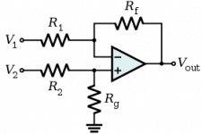
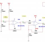
I have a high side sense resistor and am sampling it with an op-amp in a "normal" differential structure as in the first picture.
However the op-amp I am using has a common mode input voltage of Vcc-1.8V, and it inverts its output when Vin- exceeds (Vcc-1.5V) give or take.
In most other circuits I always have Vcc >> Vin, so that was never a problem.
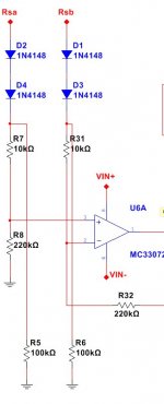
In this case I do not want to use the expense of a doubler or anything like that and was thinking of adding a couple of loaded diodes to drop the sense voltage slightly so as to be within the common voltage range. It works on the breadboard but am not sure if I can achieve the same results using fewer components or a more elegant solution?
(Other than using specially made current sense ICs like the INA series)
However the op-amp I am using has a common mode input voltage of Vcc-1.8V, and it inverts its output when Vin- exceeds (Vcc-1.5V) give or take.
In most other circuits I always have Vcc >> Vin, so that was never a problem.
In this case I do not want to use the expense of a doubler or anything like that and was thinking of adding a couple of loaded diodes to drop the sense voltage slightly so as to be within the common voltage range. It works on the breadboard but am not sure if I can achieve the same results using fewer components or a more elegant solution?
(Other than using specially made current sense ICs like the INA series)
Attachments
Plenty of opamps these days have a CM input range which includes the +ve rail. Why not add an extra transistor (MOSFET most probably) and implement a voltage-current converter powered from the rail - then no resistors need to be matched well. Just like the innards of those hi-side current sense amplifiers in fact 🙂
You might find this LT appnote interesting - http://cds.linear.com/docs/en/application-note/an105.pdf
You might find this LT appnote interesting - http://cds.linear.com/docs/en/application-note/an105.pdf
Your problem probably doesn't lie where you think it does: when you repatriate such voltages with this scheme, the common mode is also mechanically reduced unless you use very high gains.
The real problem is the matching of resistors: to avoid the much larger CM voltage leaking into the differential output, you need unpleasant levels of accuracy.
Note that most BiFET (TL08x, LF35x,etc) amps tolerate CM voltages including Vcc: although it is not guaranteed in the datasheet, it is indicated in the features (and it actually works). There is probably some reduction in performance, but it is sufficient for most applications.
Some (much more expensive) types are explicitly specified in this mode TLEsomething for example, but they are probably not required in most instances
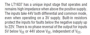
You may want to investigate "Over The Top" opamps from Linear Technology. They have a specially designed input stage which operates correctly and normally even when the opamp input voltages are above the positive supply. I've attached a couple figures


Attachments

OK, I suppose there is nothing wrong with using the TL072/TLE2072 for high side sensing and the MC33072 for low side sensing, I tested all ICs and it works fine without any special circuitry.
Maybe there is an op-amp (in DIP case) that have a common mode voltage range covering both Vcc and Vee so I do not have to use different ICs.
Edit: ahhhh LT1490 seems to be it although I was looking something in the 50 cents range like the MC33072.
Maybe there is an op-amp (in DIP case) that have a common mode voltage range covering both Vcc and Vee so I do not have to use different ICs.
Edit: ahhhh LT1490 seems to be it although I was looking something in the 50 cents range like the MC33072.
Last edited:
Any rail to rail input opampMaybe there is an op-amp (in DIP case) that have a common mode voltage range covering both Vcc and Vee so I do not have to use different ICs.
Would you believe I looked at texas, analog, st micro and linear and there is nothing short of £2 per IC, typically they are £5 or more!
The requirements are dual, +/-15V or better, rail-to-rail in.... I wonder why they are so expensive it seems they do not sell them a lot maybe.
The requirements are dual, +/-15V or better, rail-to-rail in.... I wonder why they are so expensive it seems they do not sell them a lot maybe.
Not much demand for rail-to-rail in when the total supply's 30V. The cheaper ones will be 12V and 5V operation.
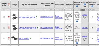
Texas Instruments offers the LM7322; it's a dual opamp, operates from ±15V supplies, Rail-to-Rail input, Rail-to-Rail output, 20 MHz, 18 Volts/usec. Digikey.co.uk sells it for £1.88 and Farnell sells it for £1.01.
Attachments

Why not use a 2-stage approach? The gain you have now is 22, pretty high. And the CM of the inputs sit at 14.3V (assuming +15V rail). I would reduce the gain to 2 or 3, which will bring the CM way down, then gain up using a 2nd stage. You can find a quad instead of a dual.
No matter what the gain, if any of the inputs is greater than Vdd or less than Vee, the output can and will behave funny, typically it will invert, unless the op-amp can accept such voltages wrt Vdd/Vee. MC33072 for low side and TL072 for high side, both cost 50p each. When we do not need perfect accuracy.
Maybe I missed something, but why would the inputs go beyond the rails if you are dividing the non-inverting (and therefore the inverting) input between Vdd and GND?
Ah now I get it, you mean something like this:
That is a great idea except I will need another stage as you have said.
That's exactly what I was thinking. To make the math simple, I thought of using a 100k/200k divider (and feedback network). This will make the 1st stage a differential amplifier with a gain of 2. The 2nd stage makes up the difference with a non-inverting amp, as you show. This opens up your choices for op-amps immensely. You don't need a rail to rail input part. I don't know your accuracy requirements but you might need to tweak the offset in the 2nd stage due to Vos being multiplied by the 2nd stage gain (11 in your case). Adding the series 10K only helps if the input current is high. I'd worry more about gaining up the Vos.
By the way, I'm curious. What is the shunt element you are sensing? And what value is it? And what are the current levels that run thru it?
That looks like an expensive part, especially Burr Brown. If you use an ordinary quad op-amp with the 2-stage approach, you dont need anything fancy in the way of CM mode range and you can cut the cost way down.
That looks like an expensive part, especially Burr Brown. If you use an ordinary quad op-amp with the 2-stage approach, you dont need anything fancy in the way of CM mode range and you can cut the cost way down.
1% resistors could give you as much as 4% error.
How accurate do you want this circuit?
What differential voltage are you expecting?
What output level are you expecting for the differential voltage?
It would be nice to know what your target is.
In circuits where I need to monitor current, eg bench PSU, battery charger etc, the op-amp is supplied with a wider voltage - this helps with sensing and with driving FETs.
This particular circuit was intended for monitoring the current of a battery operated device.
As such I did not have the luxury or board space for separate sources or for a voltage doubler and did not even think of the problem until I hit it. Fixed it with dropping in a TL072 in place.
Accuracy is not all that important, I want the circuit to cut off supply at about 2A and am using a 0.05R (two 0.1R in parallel). It does not matter if it is 2.1A or 1.95A.
The output levels are 2.5V - when the output reaches 2.5V the next op-amp simply cuts off the relay (there is a 2P2T relay). 2.5V / 22 = 113mV on the 0.05R sense resistor, equates to 2.28A.
There are two batteries in series giving a +/- 12V nominal supply, and each rail is monitored separately. The negative rail is being monitored by the MC33072 and the positive rail by the TL072.
Ideally I would use an op-amp with R-R input and output like the LM7322, OP284, LM7332, LT1490, LT1632 or a speciality IC like the INAxxx series which can be supplied 5V and sense 40V !
- Status
- Not open for further replies.
- Home
- Amplifiers
- Power Supplies
- Using inappropriate op-amp for high side sending