Just received the James Hagerman iRIAA2 inverse filter for testing my RIAA equalizer in my recently build tube amp.
Reading the manual which came with the filter, I noticed a measuring setup using a so called "FryKleaner" circuit at the front
of the iRIAA2 inverse filter. I have to confess here that I never heard about something like this "FryKleaner".
Can't I simply connect that iRIAA2 filter output to the input of the RIAA eq. then use my Gw-Instek function generator as an input source for the iRIAA2 and sweep from 20Hz to 20kHz (after adjusting the amplitude to produce a 5mV @ 1kHz at the output of that iRIAA2 filter) and look at my oscilloscope connected to the output of my RIAA
eq. circuit for a flat response?
The FryKleaner seems to be a synthesized waveform generator. It is not relevant to what you want to do:
http://www.hagtech.com/pdf/frykleaner.pdf
Just use your your inverse RIAA network as you describe. I assume the generator output impedance should be reasonably low to get an accurate result.
http://www.hagtech.com/pdf/frykleaner.pdf
Just use your your inverse RIAA network as you describe. I assume the generator output impedance should be reasonably low to get an accurate result.
That's a burn-in generator for phono preamps, and is not used otherwise.
For testing MM cartridges, the Hagerman loss at 1kHz is -40dB, or 1/100.
To get a 5mV rms to test the phono stage, set the generator output to 0.5V rms (1.4V peak to peak).
For testing MM cartridges, the Hagerman loss at 1kHz is -40dB, or 1/100.
To get a 5mV rms to test the phono stage, set the generator output to 0.5V rms (1.4V peak to peak).
Thanks Mooly and ryama for your responses. Yes, I thought that just connecting my AWG to the input and
taking care that about 5mV (I am only using a MM cartridge) is the level entering my phono stage, will do the job.
taking care that about 5mV (I am only using a MM cartridge) is the level entering my phono stage, will do the job.

Hmmm. No, can't agree with that. First of all, a square wave is visually hyper-sensitive to all sorts of changes. You can produce a bad looking square wave with a device that is actually performing well. Not really good for response testing, and can be quite misleading. And since it's nearly impossible to put a square wave on a test record, you can look at cartridge response that way either.Try using a square wave input as well. This will be more illuminating for the overall response, especially for a tube phono preamp.
If you're testing a preamp with RIAA EQ, generating the tone is a good first step, and obviously the inverse RIAA network is important. But a big part of the total response is the cartridge and its interaction with the preamp input, termination, and loading. To test total response you need a good test record. I prefer one that was recorded without RIAA EQ, which takes another level of error out of the picture. However, to make meaningful response tests using, say, the STR100, with sweeps recorded at constant amplitude up to 500Hz, the constant velocity after that, you need to know what to expect. CBS published a chart with the record. In the old days I graphed the chart on 20-20K log paper, then plotted response using a tracking response plotter. Plotter paper was thin, so you could lay the result over the target and see the deviation. Kind of a pain.
Today, what I like to do is to use the STR100, measure with REW software, but put the inverse of the published chart into REW as a cal file. The result, if your RIAA network and cartridge are spot-on, is a flat graph, made with only your RIAA network. The response correction is simply a gain/fequency file that REW reads. You can do the same thing for an inverse RIAA curve.
I think rayma was right. Feeding a square wave signal into a reverse RIAA circuitry and from this into a RIAA eq. amplifier without overdriving it, has to produce an exact square wave at the output if the eq. is designed correctly. You can even determine the RIAA amp's input capacitance this way.
Re »burning in«: Don't we need to avoid overdriving an amplifier until it catches fire?
Best regards!
Re »burning in«: Don't we need to avoid overdriving an amplifier until it catches fire?
Best regards!
The blurb says:That's a burn-in generator for phono preamps, and is not used otherwise.
So snake oil for gullible professionals !! I suppose it is reasonable for soak-testing power amps to catch the initial part of the bathtub curve, but breaking in cables?? WTF!The FryKleaner is a professional rack-mounted cable burn-in generator built to handle a big load, perfect for dealers and manufacturers. The unique analog synthesized waveforem utilizes swept and pulsed frequencies from subsonic to ultrasonic, providing a proper balance of signals to break-in both magnetic and electrical properties of cables. In other words, it works both conductors and dielectrics (insulators). Additionally, the outputs can be used for breaking in electronics, such as linestages and amplifiers.
Ok, lets assume you're going to evaluate RIAA response with a square wave. Here are 3 results. Can anyone tell exactly where in frequency the response change is and by how much?I think rayma was right. Feeding a square wave signal into a reverse RIAA circuitry and from this into a RIAA eq. amplifier without overdriving it, has to produce an exact square wave at the output if the eq. is designed correctly. You can even determine the RIAA amp's input capacitance this way.
Re »burning in«: Don't we need to avoid overdriving an amplifier until it catches fire?
Best regards!
You can do real response plots for free. No square waves, actual plots.
Attachments
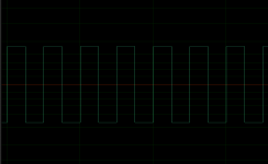
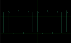

What's the square wave frequency of these plots? The 1st one is the input signal? The overshoot in the 2nd pict results from a rise towards higher frequencies. The 3rd one appears to be ok.
Best regards!
Best regards!
The second one is damped ringing(*) at a well defined frequency, its a peak in the midband I'd guess - no scale indication though so nothing can be exact from these images! Last one is missing HF, looks like a 1st order roll-off (an extra HF passive pole) - whether is in the audio band - again no scale indication on the plot.
(*) so an active filter pole pair or LC circuit, not RC passive.
(*) so an active filter pole pair or LC circuit, not RC passive.
I've been using my own inverse RIAA network for many years, and it works great.I think rayma was right. Feeding a square wave signal into a reverse RIAA circuitry and from this into a RIAA eq. amplifier without overdriving it, has to produce an exact square wave at the output if the eq. is designed correctly. You can even determine the RIAA amp's input capacitance this way.
J. Gordon Holt used his own inverse RIAA for listening to his master tapes through a DUT phono preamp.
Last edited:
How is your measuring setup?I've been using my own inverse RIAA network for many years, and it works great.
J. Gordon Holt used his own inverse RIAA for listening to his master tapes through a DUT phono preamp.
Does it make sense to connect the inv-RIAA network after the RIAA equalizer? That is the way I want to do it.
The idea of the RIAA before the phono stage is to provide a normal input signal to the phono stage,
as provided by an LP, with boosted treble and reduced bass. Then you can input a fixed level sine
wave, around 1V at all frequencies, to the inverse RIAA and the phono stage will see normal signal levels.
Connecting the inverse RIAA after the phono stage instead requires careful attention to the input level.
The bass would have to be very low in level (less than 10mV) to prevent overloading the phono stage.
Why do you want to reverse the order of the DUT and inverse RIAA?
Sorry for my late response but that inverse order has to do with the inverse RIAA network driving load at high frequencies for my signal generator if switched at the front.The idea of the RIAA before the phono stage is to provide a normal input signal to the phono stage,
as provided by an LP, with boosted treble and reduced bass. Then you can input a fixed level sine
wave, around 1V at all frequencies, to the inverse RIAA and the phono stage will see normal signal levels.
Connecting the inverse RIAA after the phono stage instead requires careful attention to the input level.
The bass would have to be very low in level (less than 10mV) to prevent overloading the phono stage.
Why do you want to reverse the order of the DUT and inverse RIAA?
I am using a (for the time being) breadboard version (working on a pcb version) of Merlin Blencowe's inverse RIAA network and found it easier signal handling to connect that
network "other way around". In the end, it will give the same result for the used RIAA network response isn't it?.
I routinely do square wave tests with an inverse RIAA circuit. There are pitfalls, but it's still revealing. Any decent square wave generator is going to have extremely fast rise and fall times. That can overload circuits that would never see such in real life. OTOH, LP pops and such can be quite fast and high amplitude, so a circuit that misbehaves with a square wave test needs further investigation. There used to be some generators with adjustable rise and fall times, Interstate was one but quite rare, and that's really useful for analog circuit testing. Once you get some experience, you can see at a glance if a RIAA stage has accuracy problems. Not quantitatively, but qualitatively. I'd suggest doing both conventional response curves and some square wave tests to get a feel for it.
Do you attenuate the generator signal level down to the 10mV region?
This would be necessary for a solid state RIAA circuit to prevent LF overloading
when putting the RIAA before the inverse RIAA.
What impedance can your signal source drive properly?
Your phono circuit may not be able to drive the input of the inverse RIAA at higher frequencies..
This would be necessary for a solid state RIAA circuit to prevent LF overloading
when putting the RIAA before the inverse RIAA.
What impedance can your signal source drive properly?
Your phono circuit may not be able to drive the input of the inverse RIAA at higher frequencies..
Sorry Conrad, I have to "digest" your valuable response.I routinely do square wave tests with an inverse RIAA circuit. There are pitfalls, but it's still revealing. Any decent square wave generator is going to have extremely fast rise and fall times. That can overload circuits that would never see such in real life. OTOH, LP pops and such can be quite fast and high amplitude, so a circuit that misbehaves with a square wave test needs further investigation. There used to be some generators with adjustable rise and fall times, Interstate was one but quite rare, and that's really useful for analog circuit testing. Once you get some experience, you can see at a glance if a RIAA stage has accuracy problems. Not quantitatively, but qualitatively. I'd suggest doing both conventional response curves and some square wave tests to get a feel for it.
1) Yes, I do.1) Do you attenuate the generator signal level down to the 10mV region?
This would be necessary for a solid state RIAA circuit to prevent LF overloading
when putting the RIAA before the inverse RIAA.
What impedance can your signal source drive properly?
2) Your phono circuit may not be able to drive the input of the inverse RIAA at higher frequencies..
2) I am preparing an active inverse RIAA pcb circuit for private use to overcome this.
- Home
- Source & Line
- Analog Line Level
- using an inverse RIAA filter