Apologies in advance for having not used something a bit neater for the schematic.
So I want to make a phono preamp with a gain of about 40 db for my turntable with ortofon 2M Bronze Cartridge. I also really love the sound of the Aikido topology (though it's not very good if you need lots of gain, which is ok, since the Ortofon cartridges are high output of about 5-5.5mV).
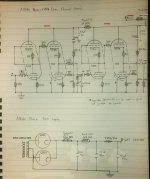
So I thought two Aikido Gain stages (both 5751 input, 6DJ8 output) at almost 30dB gain each would suffice, since the passive RIAA stage would lose me about 20dB (I used one of the ones from Tubecad.com), I would end up with almost 40 dB of gain after the RIAA stage.
Now, I also wanted a well filtered power supply, and since I'm operated on a small budget, I figured a good choke input would suffice since I wanted something well filtered and very quiet. I used PSUD2 to design it (my first time designing a power supply, so if I did anything horribly wrong, please let me know before I order and build it).
I think the schematics are good (the schematic also only shows one channel, so keep that in mind), but again, I may be horribly wrong and would like the forums input and suggestions for improvement. Thanks in advance for any help you may give.
So I want to make a phono preamp with a gain of about 40 db for my turntable with ortofon 2M Bronze Cartridge. I also really love the sound of the Aikido topology (though it's not very good if you need lots of gain, which is ok, since the Ortofon cartridges are high output of about 5-5.5mV).
So I thought two Aikido Gain stages (both 5751 input, 6DJ8 output) at almost 30dB gain each would suffice, since the passive RIAA stage would lose me about 20dB (I used one of the ones from Tubecad.com), I would end up with almost 40 dB of gain after the RIAA stage.
Now, I also wanted a well filtered power supply, and since I'm operated on a small budget, I figured a good choke input would suffice since I wanted something well filtered and very quiet. I used PSUD2 to design it (my first time designing a power supply, so if I did anything horribly wrong, please let me know before I order and build it).
I think the schematics are good (the schematic also only shows one channel, so keep that in mind), but again, I may be horribly wrong and would like the forums input and suggestions for improvement. Thanks in advance for any help you may give.
An externally hosted image should be here but it was not working when we last tested it.
Attachments
So I thought two Aikido Gain stages (both 5751 input, 6DJ8 output) at almost 30dB gain each would suffice, since the passive RIAA stage would lose me about 20dB (I used one of the ones from Tubecad.com), I would end up with almost 40 dB of gain after the RIAA stage.
You need a 1M grid resistor to ground right after the RIAA network's 1uF coupling capacitor.
This will also affect the value of the 21.6k RIAA resistor.
If the 21.6k value is correct, then the new value is: 1M x 21.6k / (1M-21.6k), or 22.077k.
So, use a 22.1k resistor.
Last edited:
Thanks for catching that 🙂You need a 1M grid resistor to ground right after the RIAA network's 1uF coupling capacitor.
This will also affect the value of the 21.6k RIAA resistor.
If the 21.6k value is correct, then the new value is: 1M x 21.6k / (1M-21.6k), or 22.077k.
So, use a 22.1k resistor.
I actually just forgot to add it into the schematic, since that RIAA network (from Tubecad) already compensates for that.
Thanks for catching that 🙂
I actually just forgot to add it into the schematic, since that RIAA network (from Tubecad) already compensates for that.
Ok, then the 21.6k value should be ok.
Bare in mind that your half-mu input stage gives you an instant 3dB noise penalty compared with a simple resistor-loaded triode. The unbypassed cathode resistor also adds noise. I don't know how important this is to you.
Here you go...
Thanks, I've already read that, but I wanted to be sure of the values I chose for everything. Plus (and this is actually the big one for me), I needed to check with the tube veterans that the power supply I designed was appropriate and quiet enough.
Bare in mind that your half-mu input stage gives you an instant 3dB noise penalty compared with a simple resistor-loaded triode. The unbypassed cathode resistor also adds noise. I don't know how important this is to you.
The more quiet the better, as far as phono amps go. Is there any reason I wouldn't want to bypass them? (I wonder what reason John Broskie wouldn't bypass them when he chose to use his topology for his phono kits.)
- Status
- Not open for further replies.
- Home
- Amplifiers
- Tubes / Valves
- Using Aikido Topology to make Phono Preamp and Power Supply