Alright, I get it now. Took a bit, and it makes sense. The impedance for our purposes for 3 tubes in ppp would be (3/4)*PrimaryZa-a for the class B load line. It's interesting, because we're accounting for the current the 3 tubes add versus one, and the reduction in coil turns, but not the fact the tube is only facing this impedance half the time, at least at this step. Most likely because we're adding the class A load line to it afterwards.
I will have to verify the corner frequency.
Thanks everyone, this was very informative!
I've given it some thought and I probably will use a 6cg7 to drive them just because I use 12ax7s in everything. I might do a 6cg7 to 6ca7 deal.
I will have to verify the corner frequency.
Thanks everyone, this was very informative!
Usually, a datasheet specifies a range for screen current, and if it's not regulated, distortion will increase when the voltage sags.
Also, I wouldn't try and use a 12AX7 to drive three EL34s. Consider buffering them with a cathode follower based on 6CG7 or the like.
I've given it some thought and I probably will use a 6cg7 to drive them just because I use 12ax7s in everything. I might do a 6cg7 to 6ca7 deal.
Last edited:
If your stuck with and going to use your 1.9K Transformer for this situation....at least try to plot it and fit it to the curves....and see what conditions make it fit best... Since it's best to look at just 2 tubes PP then your 1.9K Plate load becomes a 5.7K equivalent Plate load when you work with the curves as if it were 2 tubes PP... It's LOAD-LINE would be 1/4 of this and would be 1425 is what you draw up on the curve sheet....
If you use the next higher tap on the SECONDARY than actual load, you would get about 950 Ohms plate load...... Your inductance would be fine ....just may have less high frequency issues with leakage inductance working into a lower plate load.... But you will get your best curve fitting with this load and produce better power and better linearity...
If you use the next higher tap on the SECONDARY than actual load, you would get about 950 Ohms plate load...... Your inductance would be fine ....just may have less high frequency issues with leakage inductance working into a lower plate load.... But you will get your best curve fitting with this load and produce better power and better linearity...
Last edited:
I'm not stuck with it, I haven't ordered the Hammond or spun any bobbins. I just realized I couldn't account for the most basic aspects of the output Tx. Now that I can be more confident I am not ordering parts that I am going to fry, I can start taking more detailed advice haha.
Linearity does look like an issue at the VG2=400v because it might put the amp past the knee of the curve when swinging on the load line. I was going to lower that with a higher grid resistor thank 1k but I was also going to look into the possible effects of that on the sound. You're right though, a lower impedance would take care of this but it looks like it would be too much power. I'll have to upload my chart.
Linearity does look like an issue at the VG2=400v because it might put the amp past the knee of the curve when swinging on the load line. I was going to lower that with a higher grid resistor thank 1k but I was also going to look into the possible effects of that on the sound. You're right though, a lower impedance would take care of this but it looks like it would be too much power. I'll have to upload my chart.
Last edited:
Actually, scratch the last paragraph of my last statement.
When I draw a class B load line for (3/4)*1900ohms, it exceeds 25w dissipation. Why is this? The amp will never receive the class A portion of operation it seems. This makes me just want to lower the plate voltage to 375VDC?
The graph assumes 450V at the plate so I calculated current by 450/1425 then drew the line.
Attachments
Last edited:
Okay, I assume that exceeding 25w of the instantaneous rating is okay because the tubes only conduct in that manner for half the waveform. I am also assuming that the power tubes distort in nice ways when doing so, instead of just burning up. Poweramp overdrive sounds like an art of balancing Pdiss versus sound. At full dissipation, everything would sag anyways and the class A portion would come more into play.
I am trying to constantly relate units to keep accurate accounting. However, just doing (250mA/2)*(370v/2) gives ~22.5watts. I think what bothers me, is that RMS would reduce this by another factor of 2, so if we're talking average power, we are either far below what would hurt the tube or max tube dissipation is not relative to RMS. Or I am missing something else. I know the class A line should add into the other half of the wave form, but if we do that we have to reduce the class B side of power accounting by another factor of 2 and add in the Class A superposition. All I am trying to say from that is we would add the power from one half, then the power from the second half. RMS for either would just be (1/2*1/2Vswing)*(1/2*1/2*Iswing) then add both together to get the RMS power of the waveform, but it doesn't add to much so I know it's not inline with the convention of these drawings.
As a stipulation, the swing for either class would be it's range of operation before hitting the knee. I'm not asserting this as fact, just as my current understanding of what's happening.
As a stipulation, the swing for either class would be it's range of operation before hitting the knee. I'm not asserting this as fact, just as my current understanding of what's happening.
Last edited:
One major problem here is that the curves you are using are for 250V SCREEN VOLTAGE.... You are no where near that voltage based on the info you provided in previous threads... Keep in mind that when you draw up load-lines against curves, this represent full power output...So the voltages you will work with on the curve sheet will represent the same voltages your power supply will dip to at full power output.... Figure more like 430V on the Plates and 400V on the screens with a 480V supply at idle....Since your feeding your screens from a 1K after choke filtering from the plate supply... I base these numbers on experience and the typical power transformers available for this application.. As for plate dissipation...there are two flavors that occur.... Yo have the plate dissipation at IDLE, which is DC plate dissipation... Then when you put signal into the amp you then have AC plate dissipation when is base off the load-line and the averaging of the RMS sine-wave over the duty cycle.... But when you square wave....things change a bit...
Basically your fine in PP Class AB to assume your ON 60% of the time to approximate plate dissipation... You will never be able to operate those type of tubes in Class-A at those voltages......
Basically your fine in PP Class AB to assume your ON 60% of the time to approximate plate dissipation... You will never be able to operate those type of tubes in Class-A at those voltages......
Last edited:
Yes, I'm pretty sure Pd is average. Think of class A. If I set the idle point at PdMax, half the time it's less, and the other half it's more. In theory, a tube set at 25W and running in class A will swing between 0W and 50W, averaging 25W...
It is average, thermal time constant for an EL34 plate is far far longer than the die inside even the biggest and baddest Sanken power transistors.
Power dissipation per device maxes out at around B+^2/(2.5*Ra-a). And that happens somewhere around half power. You often (but not always) run higher quiescent.
One major problem here is that the curves you are using are for 250V SCREEN VOLTAGE.........
That's a simple correction. Take Vg2=400V. (400/250)^(3/2) is about 2. All currents are doubled. In particular, the Vg1=0 line lies twice as high, which means our loadline cuts to 20Vp instead of 80Vp, a real improvement in both maximum power and reduction of time spent over the Pdiss line.
Was class A an issue? It can easily be figured you can't be over 340V for two 20W tubes at 5,700/pair; 390V if you believe modern EL34 will cruise at 28W Pdiss (they may but six in one box seems brave).
Attachments
Yes.. the old 3/2 power law.... great for text book examples and rough approximations if your in the corner....
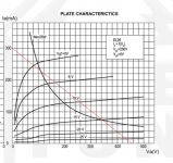
Last I plotted a good "boogie" XF2 Mullard EL34 on the Tek 570... I do remember one data point ... The 0-Bias curve hit 520mA at 170 plate volts when there was 400V on the screen... 520mA was also the spot that worked out for the Load-Line to intersect the 0-volt line..... The B+ at full-power drooped to 440V ...THis worked out to a 3.4K Plate load for 2 tubes PP ...
If you look carefully, you can see the actual EL34 curves that I plotted...
Last edited:
- Status
- This old topic is closed. If you want to reopen this topic, contact a moderator using the "Report Post" button.
- Home
- Amplifiers
- Tubes / Valves
- Using a 1900ohm OT for 6 PPP AB el34