I have read somewhere you better should match the 866A to reasonable pairs...how would you do this actually ? Is there a simple test circuit for this ? or can this be done in the amp ? They always have their 15V loss, no matter howmuch current you take from them...so how do match them ?
simply, you do not.
@Demonkleaner
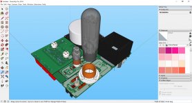
Do you´ve a photo to share. I´m finishing 211 Melomania Monobloc using two 866A (or 3B25).
JP
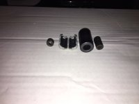
Here is a variety that I have on hand. The larger one can take a couple loops if you desire. I've never actually checked for the reduction RF hash but I've had no issues. I've have a couple of amateur radio pieces that use them. Back then there were no ferrite chokes but the power supplies were enclosed in a cage.
As far as matching, I take several known good MV's and keep switching them until I get a set that "glow alike" under load. Just for looks mind you

Attachments
One more thing. In addition to the HV delay I put a manual HV standby switch to acclimate new or recently disturbed tubes which has been stated here I think. Choke input PS is your friend.
I read here in the forumin a different 866A thread that someone uses 0,1uH, chokes, 5A for this job. I guess a little more inductance will not harm, so these guys for 2$ would be my choice I guess:
HCTI-330-5.2 Bel Signal Transformer | Mouser Deutschland
Plus in the old manuals/ data sheets you find a 10nF Cap from Anode to CT/ground. Which comes naturally when you take care of the secondary winding inductance with a quasimodo tuned snubber (see the quasimodo thread), where 10nF is the standard start point (may be 6n8 for tube circuits).
Last edited:
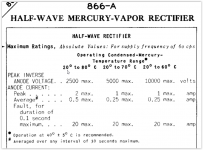
Well...it is advisable...but not a must always...depends on the tube...PSUDII is your friend...and old data sheets like this one: http://www.r-type.org/pdfs/866a.pdf
The use of a tube, for a particular project, should use the manufacturers data sheet for guidance. No two projects are usually identical, but similar.
If you are going to use a tube well below the max rating, then you could probably (broad statement) go a little higher in other areas without causing damage to a tube.
For example, in my 211 SE mono amps, I am using a CLC (20uF/10H/150uF) filter with 866A's. However, I am only drawing 100mA from the power supply with a final B+ of about 1100VDC. This use is well below the max ratings of the 866A tube and I have never had any issues in almost 17 years. 20uF is not that much capacitance (to overload an 866A), but it is enough to reduce ripple (in the first stage) for a nice CLC type power supply without having to revert to a higher plate voltage transformer.
One thing that should not be overlooked or disregarded is the advice to preheat the 866A for first time use and to preheat before use in the final circuit.
Attachments
This echoes my comment regarding PSU II is your friend...where you can simulate the peak current rating of your individual PSU. Nevertheless I believe you got to look up the data sheet of the individual brands, a Taylor may differ from a RCA.
What I found from those articles/ datasheets so far:
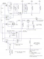
- It is important if you use FW and a 2.5V/10A winding to feed two 886A, that the socket pins are in parallel connected to the x-former. Internally the 866a is assymetrical, so it matters that both left pins are connected to the same x-former secondary connection.
- If RF is present -to be checked with a small radio - than a 1mF choke in front of each anode is recommended (Rca data sheet 82)
- and/or a 1nf to 10nf cap from secondary to CT (two times)
I will check now a couple of different types of 866a to see if thy all sound the same or not...
Theother question I would have: Why use Thyratons instead of 886A ? Just the look ? Or is there a difference in sound ?
What I found from those articles/ datasheets so far:
- It is important if you use FW and a 2.5V/10A winding to feed two 886A, that the socket pins are in parallel connected to the x-former. Internally the 866a is assymetrical, so it matters that both left pins are connected to the same x-former secondary connection.
- If RF is present -to be checked with a small radio - than a 1mF choke in front of each anode is recommended (Rca data sheet 82)
- and/or a 1nf to 10nf cap from secondary to CT (two times)
I will check now a couple of different types of 866a to see if thy all sound the same or not...
Theother question I would have: Why use Thyratons instead of 886A ? Just the look ? Or is there a difference in sound ?
Last edited:
thys´ have lower ua rating, so for hv you need diodes.
i successfully tried hybrid bridge with neg grid supply
it does regulate by self the output voltage. in a crude matter, but nice.
0v ug = diode, anything else adjusts breakdown ua-k; think like a adjustable diac (15-1300v) in series with diode.
actually gas tubes are more like one way diacs 15-20v
i successfully tried hybrid bridge with neg grid supply
it does regulate by self the output voltage. in a crude matter, but nice.
0v ug = diode, anything else adjusts breakdown ua-k; think like a adjustable diac (15-1300v) in series with diode.
actually gas tubes are more like one way diacs 15-20v
This echoes my comment regarding PSU II is your friend...where you can simulate the peak current rating of your individual PSU. Nevertheless I believe you got to look up the data sheet of the individual brands, a Taylor may differ from a RCA.
What I found from those articles/ datasheets so far:
- It is important if you use FW and a 2.5V/10A winding to feed two 886A, that the socket pins are in parallel connected to the x-former. Internally the 866a is assymetrical, so it matters that both left pins are connected to the same x-former secondary connection.
- If RF is present -to be checked with a small radio - than a 1mF choke in front of each anode is recommended (Rca data sheet 82)
- and/or a 1nf to 10nf cap from secondary to CT (two times)
I will check now a couple of different types of 866a to see if thy all sound the same or not...
Theother question I would have: Why use Thyratons instead of 886A ? Just the look ? Or is there a difference in sound ?
Hi ... i tried with psud II but the values not is correct for the 866. PSUD not is my friend in this case.
So i'm working two 866 with C input (10uF) L (20H) C (47uF) ... 450-0-450v for 420V and 130mA output. Following the dasheet an suitable R on the plates has been necessary.
- Status
- Not open for further replies.
- Home
- Amplifiers
- Tubes / Valves
- Using 866A Mercury Vapour Rectifiers?